Device for measuring flatness and parallelism of disc parts

A technology of flatness and parallelism, which is applied in the field of devices for flatness and parallelism measurement of disc parts, can solve the problems of complex operation, large size, high-precision flat crystal bottleneck, high maintenance cost, etc., and achieve simple structure of the device, Improved stability and ease of operation

Active Publication Date: 2017-01-25
INST OF MACHINERY MFG TECH CHINA ACAD OF ENG PHYSICS
View PDF9 Cites 15 Cited by
  • Summary
  • Abstract
  • Description
  • Claims
  • Application Information

AI Technical Summary

Problems solved by technology

However, its measurement range is limited by the size of the flat crystal, and large-size, high-precision flat crystals have always been the bottleneck in the industry
At the same time, laser interferometers have high requirements on environmental humidity, temperature

Method used


Image

  • Device for measuring flatness and parallelism of disc parts
  • Device for measuring flatness and parallelism of disc parts

Examples


Example Embodiment

[0021] Example 1

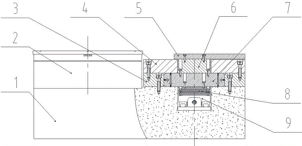
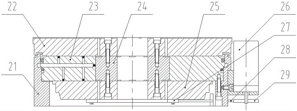
[0022] figure 1 It is a schematic diagram of the device structure for measuring the flatness and parallelism of disc-like parts according to the present invention, figure 2 It is a schematic diagram of the structure of the gas static pressure turntable unit in the present invention. in figure 1 , 2 In the present invention, a device for measuring the flatness and parallelism of disc-like parts includes a base 1, a gas static pressure linear guide unit, a gas static pressure turntable unit 2 and a displacement sensor, wherein the gas static pressure The pressing linear guide unit includes a side guide rail 3, an upper guide rail 4, a carrying plate 5, a connecting plate 6, a slider 7, a flexible connector 8 and a ball screw 9. The gas static pressure turntable unit 2 includes a housing 21, an upper thrust plate 22, a throttle 23, a rotor 24, a lower thrust plate 25, a pulley I 27, a timing belt 28 and a pulley II 29. The connection relationship is that the ga...

Example Embodiment

[0038] Example 2

[0039] The basic structure of this embodiment is the same as that of embodiment 1. The difference is that there are two displacement sensors, which are installed relative to each other. One is in contact with the upper surface of the part and the reading is x1, and the other is in contact with the lower surface of the part, and the reading is x2, the obtained position coordinates of the sampling point and the part surface data constitute a four-dimensional array (r, a, x1, x2), and the parallelism error is obtained by calculation.

[0040] The displacement sensor adopts the Swiss TESA precision capacitance displacement sensor.

[0041] The material of the base 1 is marble.

[0042] The measured parallelism result of the test piece is 2.5um.


PUM

PropertyMeasurementUnit
Flatnessaaaaaaaaaa
Parallelismaaaaaaaaaa

Abstract

The invention discloses a device for measuring flatness and parallelism of disc parts. Measuring is performed by acquiring data at different sites based on motion under a polar coordination system; the polar diameter movement under the polar coordination system is realized through statically pressed linear guideway by the air, while the pole angular movement is realized through statically pressed rotary table by the air; the guideway adopts a flexible connector to drive to improve movement precision; the rotary table adopts a reduction design to improve stability of the device; the guideway and the rotary table are independently fixed on a base to form a measurement standard of precision polar coordinate system, avoiding measuring error caused by coupling of compound motion. During measurement, workpieces are arranged on the statically pressed rotary table by the air for rotary movement, while a displacement sensor is arranged on the statically pressed linear guideway by the air for linear movement; and the displacement sensor returns relative height data of the surface of the tooling, and the flatness and parallelism of the tooling are obtained through fitting calculation. The device is simple in structure and convenient to operate and is applicable to measuring flatness and parallelism of disc parts on site under complex industrial environment.

Description

technical field [0001] The invention belongs to the field of measurement, and in particular relates to a device for measuring the flatness and parallelism of disc parts. Background technique [0002] With the development of industrial technology, the demand for precision parts is becoming more and more urgent, especially for disc and rotary mechanical moving parts. Common indicators to characterize the accuracy of such parts are flatness and parallelism. At present, the measurement of flatness and parallelism of many disk parts relies on three-coordinate measuring machines and laser interferometers. [0003] Three-coordinate measuring machines are most widely used in flatness and parallelism measurement. The three-coordinate measuring machine fits the surface topography of the workpiece by measuring points in space, and can adapt to most shape and position accuracy measurements. However, because the X, Y, and Z axes are connected in series, resulting in error transmission...

Claims


Application Information

Patent Timeline
IPC IPC(8): G01B21/30G01B21/22G01B7/34G01B7/30
CPCG01B7/30G01B7/34G01B21/22G01B21/30
Inventor 张小强钱志强夏欢俞利庆易忠全
Owner INST OF MACHINERY MFG TECH CHINA ACAD OF ENG PHYSICS
Why Eureka
Try Eureka