Auxiliary positioning mechanism of connector, connector seat body and terminal equipment

An auxiliary positioning and terminal equipment technology, which is applied to the parts, connections, and fixed connections of the connecting device. It can solve the problems of terminal equipment power failure, back loose, and slight deviation of the connector male seat 1, so as to facilitate disassembly. , simple preparation process and stable signal transmission

Active Publication Date: 2017-02-01
GUANGDONG HONGQIN COMM TECH CO LTD
8 Cites 0 Cited by

AI-Extracted Technical Summary

Problems solved by technology

However, in the absence of any positioning structure to limit the connector male seat 1, when the terminal device is dropped or shaken, etc., when the connector is impacted by an external force, the connector male seat 1 may be sligh...

Method used

Compared with the prior art, the auxiliary positioning mechanism of the connector provided in this embodiment, when the connector male seat is inserted into the connector female seat, the positioning member can accurately position the connector male seat, and when the terminal device falls Or when the connector is impacted by external force due to vibration or other conditions, it can effectively prevent the connector male seat from slightly shifting or retreating and loosening, so as to ensure the stable signal transmission of the connector pins. Furthermore, the positioning member 7 is formed with a limiting portion that can match the contour of the abutting portion, which further improves the stability of positioning.
In the present embodiment, preferably, the number of positioning unit can be two; The abutting portion 81 makes the positioning more stable. However, this embodiment does not impose any limitation on the specific number of positioning units.
It is not difficult to see that the present embodiment provides a specific implementation of the connection structure 6, that is, the positioning member 7 and the base 5 are rotatably connected, and this kind of connection is relatively simple. Compared with the detachable connection, The positioning member 7 forms a non-detachable integral body with the base 5 through the rotating shaft 61 , the whole is relatively simple and the positioning member 7 is not easy to lose.
[0034] In this embodiment, preferably, the positioning member 7 is formed with a limit portion 71 that matches the contour of the abutting portion 81, and when the positioning member 7 is in the first position, the abutting portion 81 is located in the limit portion 71. In fact, the limiting part 71 is a groove, when the positioning part 7 is held against the connector male seat 8 and positioned in the connector female seat 4, since the limiting part 71 can match the connector male seat 8 The abutting portion 81, so that the abutting portion 81 is located in the groove of the limiting portion 71, so that the limiting portion 71 can be in contact with the two surfaces of the abutting portion 81, furt...

Abstract

The invention relates to the field of electronic equipment and discloses an auxiliary positioning mechanism of a connector, a connector seat body and terminal equipment. According to the embodiment of the invention, the auxiliary positioning mechanism of the connector comprises at least one positioning unit, wherein the at least one positioning unit is located at one side of a connector female seat and comprises a base, a connection structure and a positioning part; the positioning part is connected to the base through the connection structure; the positioning part is provided with a first position and a second position relative to the base; when the positioning part is located at the first position, the positioning part is propped against a butting part of a connector male seat to position the connector male seat on the connector female seat; and when the positioning part is located at the second position, the positioning part is located outside a plug moving region of the connector male seat. The invention further discloses a connector seat body and terminal equipment. According to the auxiliary positioning mechanism of the connector, the connector seat body and the terminal equipment, the deviation or retreating looseness phenomenon is avoided to the greatest extent when the connector male seat is impacted by external force, thereby ensuring stable transmission of a pin signal of a connector end and normal use of a mobile terminal.

Application Domain

Coupling device detailsFixed connections

Technology Topic

EngineeringElectronic equipment +1

Image

  • Auxiliary positioning mechanism of connector, connector seat body and terminal equipment
  • Auxiliary positioning mechanism of connector, connector seat body and terminal equipment
  • Auxiliary positioning mechanism of connector, connector seat body and terminal equipment

Examples

  • Experimental program(1)

Example Embodiment

[0028] In order to make the object, technical solution and advantages of the present invention clearer, various embodiments of the present invention will be described in detail below in conjunction with the accompanying drawings. However, those of ordinary skill in the art can understand that, in each implementation manner of the present invention, many technical details are provided for readers to better understand the present application. However, even without these technical details and various changes and modifications based on the following implementation modes, the technical solution claimed in this application can also be realized.
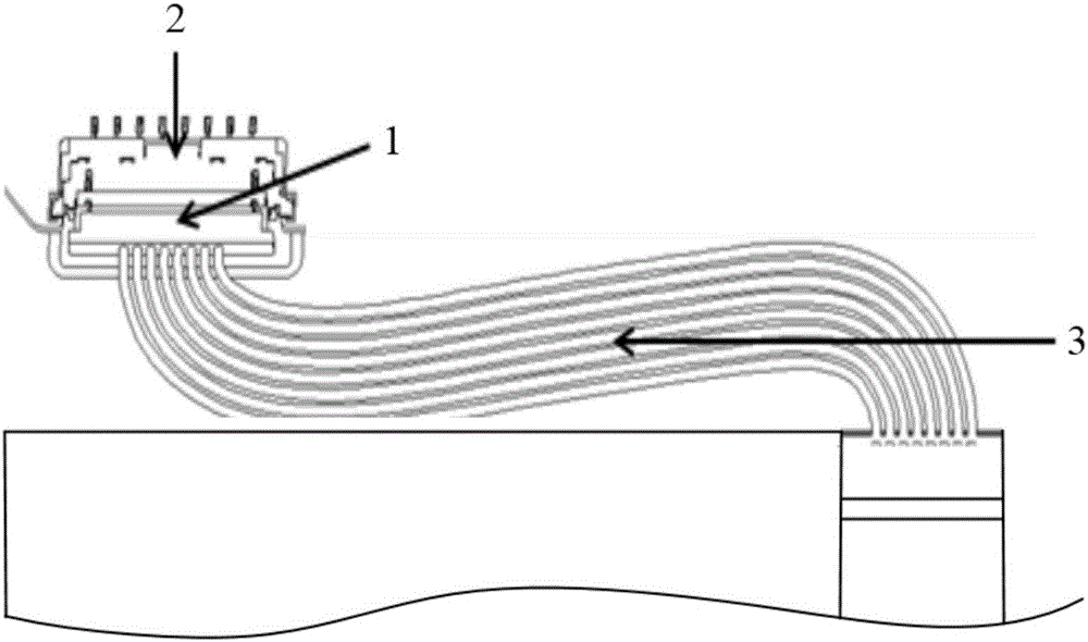
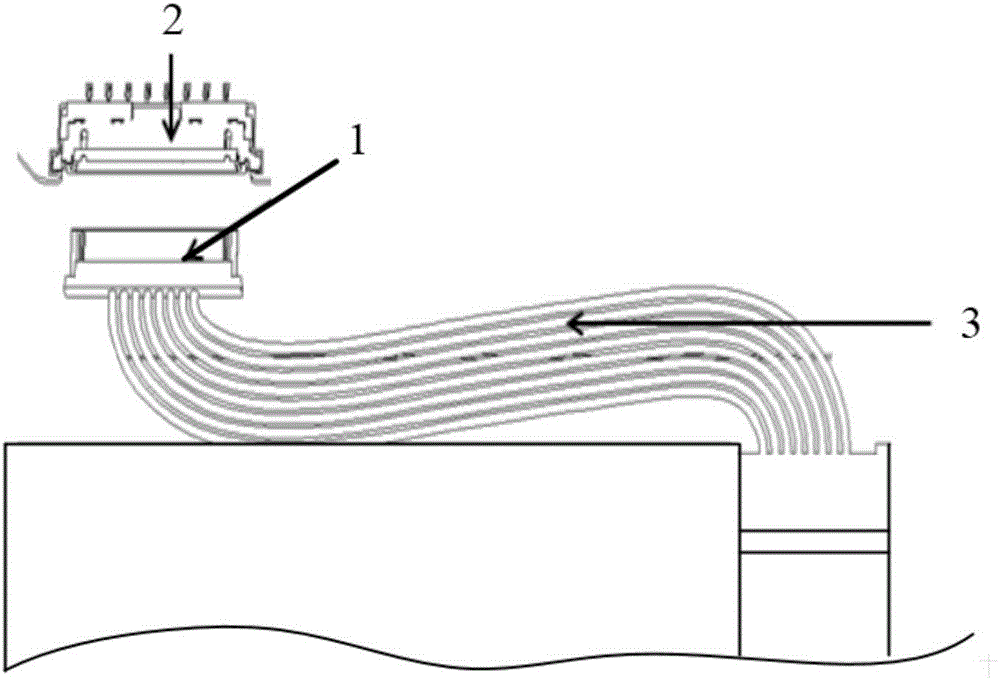
[0029] The first embodiment of the present invention relates to an auxiliary positioning mechanism for a connector, which is used to assist the positioning of the connector male seat on the connector female seat; wherein, the connector male seat and the connector female seat are, for example, wire-to-board connectors The male and female sockets, the wire-to-board connector can be used as a battery connector in terminal devices such as smartphones, tablet computers, and notebook computers; however, this embodiment does not impose any restrictions on this.
[0030] Please refer to image 3 , Figure 4 , in this embodiment, the male connector seat 8 and the female connector seat 4 are plug-in mated, that is, the female connector seat 4 does not move, and the male connector seat 8 is pluggably connected to the female connector seat 4 . The connector male seat 8 has a plug-in movement area relative to the connector female seat 4, and the plug-in movement area is the retreat of the connector male seat 8 when the connector male seat 8 is pulled out of the connector female seat 4. space. In practice, the length of the plug-in movement area in the plugging direction of the connector male seat 8 may be greater than or equal to the length of the connector male seat 8 inserted into the connector female seat 4, so as to ensure that the connector male seat 8 has sufficient retreat The space ensures that the male connector seat 8 can be completely pulled out from the female connector seat 4.
[0031] In this embodiment, the auxiliary positioning mechanism of the connector includes: at least one positioning unit, which is located on one side of the connector base 4 and includes a base 5 , a connecting structure 6 and a positioning member 7 .
[0032] The positioning piece 7 is connected to the base 5 through the connection structure 6, and the positioning piece 7 has a first position and a second position relative to the base 5; wherein, when the positioning piece 7 is in the first position, the positioning piece 7 is against the connector male The abutting portion 81 of the seat 8 is used to position the male connector seat 8 on the female connector seat 4;
[0033] In this embodiment, preferably, the number of positioning units can be two; the two positioning units are respectively arranged on the opposite sides of the connector female seat 4, so as to abut against the two abutting parts of the connector male seat 8 respectively. 81, making the positioning more stable. However, this embodiment does not impose any limitation on the specific number of positioning units.
[0034] In this embodiment, preferably, the positioning member 7 is formed with a limiting portion 71 matching the profile of the abutting portion 81 , and when the positioning member 7 is in the first position, the abutting portion 81 is located in the limiting portion 71 . In fact, the limiting part 71 is a groove, when the positioning part 7 is held against the connector male seat 8 and positioned in the connector female seat 4, since the limiting part 71 can match the connector male seat 8 The abutting portion 81, so that the abutting portion 81 is located in the groove of the limiting portion 71, so that the limiting portion 71 can be in contact with the two surfaces of the abutting portion 81, further enhances the stability of positioning, and helps to prevent connection The male seat 8 recedes and loosens and shifts left and right, thereby enhancing the stability of positioning; wherein, the limiting part 71 can be formed by in-mold injection molding of the positioning part 7, and the preparation process is relatively simple.
[0035] In this embodiment, the connecting structure 6 includes a rotating shaft 61 ; the positioning member 7 is rotatably connected to the base 5 through the rotating shaft 61 .
[0036]Preferably, the rotating shaft 61 can extend from the positioning member 7 ; the rotating shaft 61 is rotatably connected to the base 5 . In practice, the rotating shaft 61 extends from two opposite sides of the positioning member 7; the base 5 is formed with a positioning groove that can match the rotating shaft 61, and the rotating shaft 61 can be engaged in the positioning groove, and the groove of the positioning groove The opening can limit the rotating shaft 61 so that the rotating shaft 61 will not slip out of the positioning slot 51 , so that the positioning member 7 is rotatably connected to the base 5 through the rotating shaft 61 .
[0037] Alternatively, the positioning member 7 and the rotating shaft 61 can be prepared separately, for example, the rotating shaft 61 can be fixed on the base 5 or extend from the base 5; the positioning member 7 is rotatably connected to the rotating shaft 61, that is, one end of the positioning member 7 There is a through hole through which the rotating shaft 61 can pass, so that the positioning member 7 is rotatably connected to the base 5 through the rotating shaft 61 .
[0038] It is not difficult to see that this embodiment provides a specific implementation of the connection structure 6, that is, the positioning member 7 is rotatably connected to the base 5, and this connection method is relatively simple. Compared with the detachable connection, the positioning member 7 The rotating shaft 61 and the base 5 form a non-detachable integral body, the whole is relatively simple and the positioning member 7 is not easily lost.
[0039] In this embodiment, preferably, the connecting structure 6 may further include a stopper 62; when the positioning member 7 is in the first position, the first side of the positioning member 7 is abutted against the abutment portion 81 of the connector male seat 8, The second side opposite to the first side is against the stopper 62 . In this embodiment, when the positioning member 7 is in the first position, the position of the stopper 62 is defined. When the connector male seat 8 is inserted into the connector female seat 4, the positioning member 7 is positioned at the first position, and the positioning member 7 positions the connector male seat 8 in the connector female seat 4. At this time, the positioning member 7 and the connector The contacting surface of the abutting portion 81 of the male seat 8 is the first side, and the side opposite to the first side is the second side; the second side is abutted against the stopper 62 .
[0040] It is not difficult to see that the setting of the stopper 62 makes it possible to further stop the positioning member 7 on the basis of the positioning of the connector male seat 8 by the positioning member 7, so as to prevent the connector male seat 8 from receding due to the loosening of the positioning member 7. The phenomenon of loosening makes the positioning more stable.
[0041] Compared with the prior art, the auxiliary positioning mechanism of the connector provided in this embodiment, when the connector male seat is inserted into the connector female seat, the positioning member can accurately position the connector male seat, and the terminal device falls or shakes, etc. In some cases, when the connector is impacted by external force, it can effectively prevent the connector male seat from slightly shifting or retreating and loosening, so as to ensure the stable signal transmission of the connector pins. Furthermore, the positioning member 7 is formed with a limiting portion that can match the contour of the abutting portion, which further improves the stability of positioning.
[0042] The second embodiment of the present invention relates to an auxiliary positioning mechanism of a connector. This embodiment is substantially the same as the first embodiment, the main difference is that: in the first embodiment, the connecting structure 6 includes a rotating shaft 61, and the positioning member 7 is rotatably connected to the base 5 through the rotating shaft 61; In this embodiment, the connecting structure 6 includes a first engaging portion and a second engaging portion respectively disposed on the base 5 and the positioning member 7. The positioning member 7 is detachably connected to the base 5. Please refer to image 3.
[0043] When the second engaging portion engages with the first engaging portion, the positioning member 7 is located at the first position; when the second engaging portion disengages from the first engaging portion, the positioning member 7 is located at the second position. Wherein, the first engaging portion and the second engaging portion are, for example, the cooperation between a groove and a hook; this embodiment does not impose any limitation on this.
[0044] Specifically, when the second engaging part is engaged with the first engaging part, that is, the positioning part 7 is connected to the base 5, at this time, the positioning part 7 positions the connector male seat 8 in the connector female seat 4 ; When the second engaging part is separated from the first engaging part, that is, the positioning part 7 is disassembled from the base 5, and the positioning part 7 is located outside the plugging and unplugging movement area of ​​the connector male seat 8 to ensure that the connector works 7 has enough receding space relative to the connector female seat 4, so that the connector male seat 8 can be completely pulled out from the connector female seat 4.
[0045] It is not difficult to see that this embodiment provides another specific realization of the connection structure, that is, the positioning member and the base are detachably connected, and the connection method is relatively simple. Of course, in practice, those skilled in the art can set according to the actual needs of the terminal device or the user.
[0046] The third embodiment of the present invention relates to an auxiliary positioning mechanism of a connector. This embodiment is substantially the same as the first embodiment, the main difference is that: in the first embodiment, the connecting structure 6 includes a rotating shaft 61, and the positioning member 7 is rotatably connected to the base 5 through the rotating shaft 61; In this embodiment, if Figure 5 As shown, the connection structure 6 includes a slide rail 51 disposed on the base 5 and a slider 72 disposed on the positioning member 7 , and the positioning member 7 is slidably disposed on the base 5 through the cooperation of the slide block 72 and the slide rail 51 .
[0047] Specifically, the sliding block 72 of the positioning member 7 has a first position and a second position relative to the sliding rail 51 of the base 5, wherein, when the sliding block 72 is in the first position, the positioning member 7 is against the male connector seat 8 The abutting portion 81 of the connector male seat 8 is positioned on the connector female seat 4; when the slider 72 slides to the second position, the positioning member 7 is located outside the plug-in movement area of ​​the connector male seat 8, so that the connection The work 8 of the connector has enough back space to ensure that the connector male seat 8 is completely pulled out from the connector female seat 4 .
[0048] It should be noted that in this embodiment, there is no limitation on the specific structure of the slider 72 and the slide rail 51 , and any structural form that can realize the sliding of the positioning member 7 relative to the base 5 is applicable to this embodiment.
[0049] It is not difficult to see that in this embodiment, the positioning member can be slidably arranged on the base through the slider and the slide rail, which provides another way for the positioning member to be connected to the base. Those skilled in the art can The actual needs of users are set.
[0050] The fourth embodiment of the present invention relates to a connector base, which can be applied to terminal devices such as smart phones, tablet computers, and notebook computers. The connector seat in this embodiment includes: the connector base 4 and the auxiliary positioning mechanism of the connector in any one of the first to third embodiments, such as Image 6 shown.
[0051] The base 5 of the auxiliary positioning mechanism is extended from the shell 41 of the connector base 4 . Specifically, a connecting piece 411 is extended from the housing 41, and the connecting piece 411 is further extended to form the base 5; in practice, the base 5 can be formed by in-molding the housing 41 of the connector female base 4, that is, in the preparation When the housing 41 of the connector female base 4 is prepared, the base 5 can be prepared together. Compared with the base 5 independently prepared for the auxiliary positioning mechanism, the number of molds can be reduced, thereby saving the cost of mold opening; and, it can be reduced The number of components, easy to assemble.
[0052] The shell 41 of the connector base 4 generally includes a metal part and an insulating part. Preferably, the base 5 of the auxiliary positioning mechanism can be formed by extending the insulating part of the housing 41 . Of course, in practice, the base 5 can also be formed by extending the metal part of the housing 41 , but this embodiment does not impose any limitation on this, and those skilled in the art can set it according to the actual needs of terminal equipment or users.
[0053] Compared with the prior art, the connector seat body provided by this embodiment, when the male connector seat is inserted into the female connector seat, the locating member can precisely position the male connector seat, and when the terminal device falls or vibrates, etc. , when the connector is impacted by external force, it can effectively prevent the connector male seat from shifting or retreating and loosening, and ensure the stable signal transmission of the connector end pins; the base is formed by the extension of the shell of the connector female seat, and the formation method It is relatively simple, helps to reduce economic costs, and can reduce the number of components and parts, and facilitates assembly.
[0054] A fifth embodiment of the present invention relates to a terminal device, such as a smart phone, a tablet computer, a notebook computer, and the like. like Figure 7 As shown, the terminal device in this embodiment includes: a housing 9, a circuit board (not shown in the figure), a connector base 4, and an auxiliary positioning mechanism for the connector in any one of the first to third embodiments.
[0055] The base 5 is disposed on the first surface of the housing 9 , the circuit board is fixed on the second surface of the housing 9 ; the connector base 4 is installed on the circuit board and exposed on the first surface of the housing 9 .
[0056] Specifically, the housing 9 of the terminal device includes a first surface and a second surface opposite to the first surface, the housing 9 has an opening, the connector base 4 is installed on the circuit board, and passes through the opening of the housing 9 , exposing the first surface of the housing 9 , the circuit board is fixed on the second surface of the housing 9 ; the base 5 is disposed on the first surface of the housing 9 .
[0057] Preferably, in this embodiment, the base 5 can be integrally formed on the housing 9, that is, when the housing 9 is prepared, the base 5 can be used together. Compared with the base of the auxiliary positioning mechanism prepared independently, The number of molds can be reduced, thereby saving mold opening costs; moreover, the number of components can be reduced to facilitate assembly.
[0058] In this embodiment, the female connector seat is the female seat of the battery connector. Specifically, the terminal device also includes: a rechargeable battery 10 and a connector male seat 8, that is, the connector male seat 8 is extended from the rechargeable battery 10, and the connector male seat 8 and the connector female seat 4 serve as the battery connector. Male and female seats. Wherein, the rechargeable battery 10 is fixed on the first surface of the housing 9; the rechargeable battery 10 is connected to the circuit board through the connector male seat 8 and the connector female seat 4, so that the rechargeable battery 10 can provide working power for the circuit board .
[0059] In this embodiment, the specific application scenarios of the female connector seat 4 and the male connector seat 8 are not limited in any way; they can also be used as electrical connections for other electronic components.
[0060] Compared with the prior art, in the terminal device provided by this embodiment, when the connector male seat is inserted into the connector female seat, the positioning member can accurately position the connector male seat. When subjected to external impact, it can effectively prevent the connector male seat from shifting or retreating and loosening, and ensure the stable signal transmission of the connector end pins; moreover, for the connector as a "wire-to-board battery connector", This embodiment provides an implementation manner of an auxiliary positioning mechanism suitable for a connector of a rechargeable battery.
[0061] Those of ordinary skill in the art can understand that the above-mentioned embodiments are specific examples for realizing the present invention, and in practical applications, various changes can be made to it in form and details without departing from the spirit and spirit of the present invention. scope.

PUM

no PUM

Description & Claims & Application Information

We can also present the details of the Description, Claims and Application information to help users get a comprehensive understanding of the technical details of the patent, such as background art, summary of invention, brief description of drawings, description of embodiments, and other original content. On the other hand, users can also determine the specific scope of protection of the technology through the list of claims; as well as understand the changes in the life cycle of the technology with the presentation of the patent timeline. Login to view more.

Similar technology patents

Motor car broadcast simulation system

InactiveCN105845147Aimprove sound qualitySignal transmission is stable
Owner:CHENGDU ZERO LINE TECH CO LTD

Fixed bed adsorption reactor

InactiveCN101966439AEasy to disassembleeasy to fill
Owner:XIAMEN UNIV

Monitor for electricity utilization

InactiveCN104730390ASignal transmission is stableSolve the inconvenience of wiring
Owner:QINGDAO DONGRUAN ZAIBO INTELLIGENT ELECTRONICS

Suspended ceiling structure for mobile house

ActiveCN101158196AEasy to disassemble
Owner:华南建材(深圳)有限公司

Water pump

ActiveCN106246603AEnhanced resistance to wear and corrosionEasy to disassemble
Owner:青木川环保科技(广州)有限公司

Array substrate

InactiveCN107315289ACompensate for reduced charge transport rateSignal transmission is stable
Owner:TCL CHINA STAR OPTOELECTRONICS TECH CO LTD

Fire extinguisher management system

PendingCN108310713Aimprove accuracySignal transmission is stable
Owner:四川久天测控技术有限公司

Classification and recommendation of technical efficacy words

  • Signal transmission is stable
  • Easy to disassemble

Array substrate

InactiveCN107315289ACompensate for reduced charge transport rateSignal transmission is stable
Owner:TCL CHINA STAR OPTOELECTRONICS TECH CO LTD

Monitor for electricity utilization

InactiveCN104730390ASignal transmission is stableSolve the inconvenience of wiring
Owner:QINGDAO DONGRUAN ZAIBO INTELLIGENT ELECTRONICS

Fire extinguisher management system

PendingCN108310713Aimprove accuracySignal transmission is stable
Owner:四川久天测控技术有限公司

Motor car broadcast simulation system

InactiveCN105845147Aimprove sound qualitySignal transmission is stable
Owner:CHENGDU ZERO LINE TECH CO LTD

Novel ceiling mounting structure

Owner:上海西蒙铝业有限公司

Inspection robot for underground coal mine

Owner:安徽玄离智能科技股份有限公司

Multistep assemblied anti-settle magnetic rheological damper

InactiveCN1869470AEasy to disassembleSimple processing design
Owner:TIANJIN UNIV
Why Eureka
Try Eureka