Steering drive device and seepage-preventing ditch cast-in-situ forming machine

A technology of driving device and driving parts, which is applied in water conservancy projects, artificial waterways, buildings, etc., can solve the problems of being unable to fully utilize the working potential of anti-seepage canal cast-in-place forming equipment, unable to realize steering work, and large work limitations, etc., to achieve The effect of reducing work limitations, simple structure, and large work potential

Active Publication Date: 2017-02-08
YANCHENG XINSUYUAN MACHINERY MFG
View PDF5 Cites 4 Cited by
  • Summary
  • Abstract
  • Description
  • Claims
  • Application Information

AI Technical Summary

Problems solved by technology

During the pouring process of the channel, the rollers of the forming machine body are in contact with the ground to realize walking, and can only walk in a straight line, and cannot realize steering work. The work is limited, and the full working potential of the anti-seepage canal cast-in-place forming equipment cannot be fully utilized
In order to realize the steering of the anti-seepage canal cast-in-place forming machine, it is necessary to install a relatively complicated driving device on the forming machine body

Method used


Image

  • Steering drive device and seepage-preventing ditch cast-in-situ forming machine
  • Steering drive device and seepage-preventing ditch cast-in-situ forming machine
  • Steering drive device and seepage-preventing ditch cast-in-situ forming machine

Examples


Embodiment 1

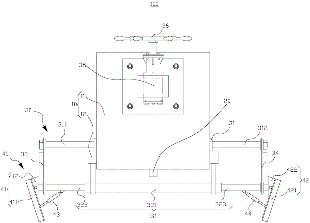
[0040] Such as figure 1 As shown, a steering drive device 100 provided in this embodiment includes a base 10 , a first drive member 20 , a second drive member 30 and an actuator assembly 40 .

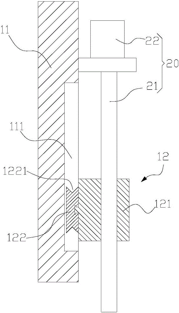
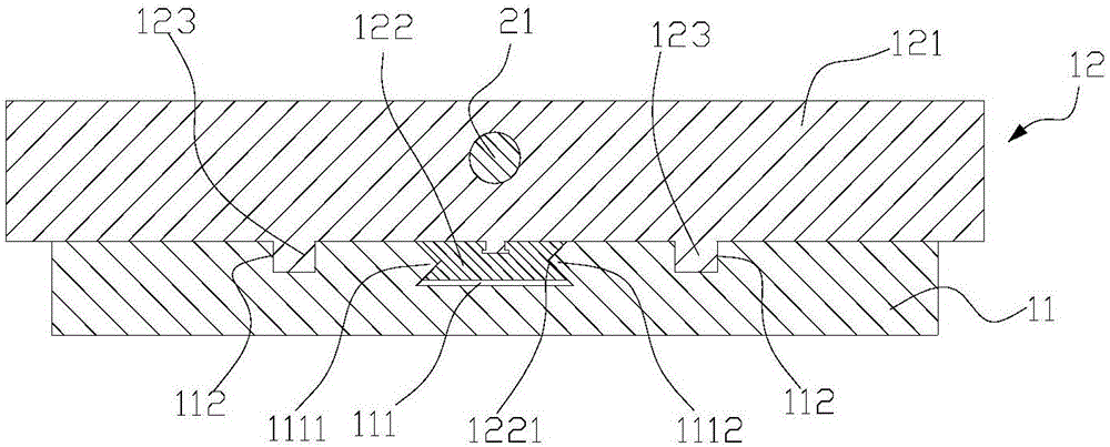
[0041] Such as figure 2 , image 3 The shown base 10 includes a fixed base 11 and a movable base 12 , the movable base 12 is slidably connected with the fixed base 11 , and the first driving member 20 is used to drive the movable base 12 to slide vertically relative to the fixed base 11 .

[0042] Wherein, in this embodiment, the fixing seat 11 is a plate-shaped structure, and a first chute 111 and a second chute 112 arranged vertically are opened on one side thereof, and in this embodiment, there are two second chute 112 , the two second chute 112 are parallel to each other, the first chute 111 is located in the middle of the two parallel second chute 112, the first chute 111 is parallel to the second chute 112, the cross section of the second chute 112 is U-shaped. The first chut...

Embodiment 2

[0058] Such as Image 6 As shown, this embodiment provides an anti-seepage canal cast-in-place forming machine 200, which includes a forming machine body 201, a walking assembly 202, and the steering drive device 100 in the above-mentioned embodiments.

[0059] Wherein, the forming machine body 201 can complete the pouring work of the channel, so that the channel will not leak. The specific structure of the molding machine body 201 is the same as that of the prior art. Of course, the molding machine body 201 should be provided with an oil supply system for supplying oil to each hydraulic element.

[0060] Such as Figure 7 As shown, the walking assembly 202 includes a first walking part 203, a second walking part 204, a first connecting rod 205 and a second connecting rod 206, the first walking part 203 is parallel to the second walking part 204, and the first connecting rod 205 The two ends are respectively hinged with the first running part 203 and the second running part...


PUM


Abstract

The invention provides a steering drive device and a seepage-preventing ditch cast-in-situ forming machine and belongs to the field of agricultural machines. The steering drive device comprises a base, a first drive part, a second drive part and an executing assembly. The base comprises a fixed seat and a movable seat. The movable seat is connected with the fixed seat in a sliding manner. The first drive part can drive the movable seat to slide in the vertical direction relative to the fixed seat. The second drive part is fixed to the movable seat. The executing assembly is connected with the second drive part. The executing assembly comprises a first stirring piece and a second stirring piece. The second drive part can drive the first stirring piece and the second stirring piece to move back and forth relative to the base in the same direction in the horizontal plane. The drive device has the beneficial effects of being simple in structure and good in operability. The seepage-preventing ditch cast-in-situ forming machine with the drive device has a certain steering function, the work limitation of the seepage-preventing ditch cast-in-situ forming machine is lowered, and the seepage-preventing ditch cast-in-situ forming machine can exert greater work potential.

Description

technical field [0001] The invention relates to the field of agricultural machinery, in particular to a steering drive device and an anti-seepage canal cast-in-place forming machine. Background technique [0002] At present, the whole society vigorously promotes the measures of water-saving irrigation, and the anti-seepage canal is an important part of water-saving irrigation. The anti-seepage canal can be poured and formed by the anti-seepage canal cast-in-place forming machine. The existing anti-seepage canal cast-in-place forming machine includes a forming machine body and rollers located at the bottom of the forming machine body. The forming machine body can complete the pouring action, and the rollers drive The molding machine body moves. During the pouring process of the channel, the rollers of the forming machine body are in contact with the ground to realize walking, and can only walk in a straight line, and cannot realize steering work. The work is limited, and the...

Claims


Application Information

Patent Timeline
Patent Type & Authority Applications(China)
IPC IPC(8): E02B5/02
CPCE02B5/02
Inventor 赵振秀孙素元汤沛孙建东夏基胜
Owner YANCHENG XINSUYUAN MACHINERY MFG
Why Eureka
Try Eureka