power conversion device
A technology of power conversion device and power conversion circuit, which is applied in the direction of output power conversion device, electrical components, etc., can solve the problem that the temperature of the frame body rises to high temperature, and achieve the effect of reducing mutual inductance and eddy current
- Summary
- Abstract
- Description
- Claims
- Application Information
AI Technical Summary
Problems solved by technology
Method used
Image


Examples
Embodiment 1
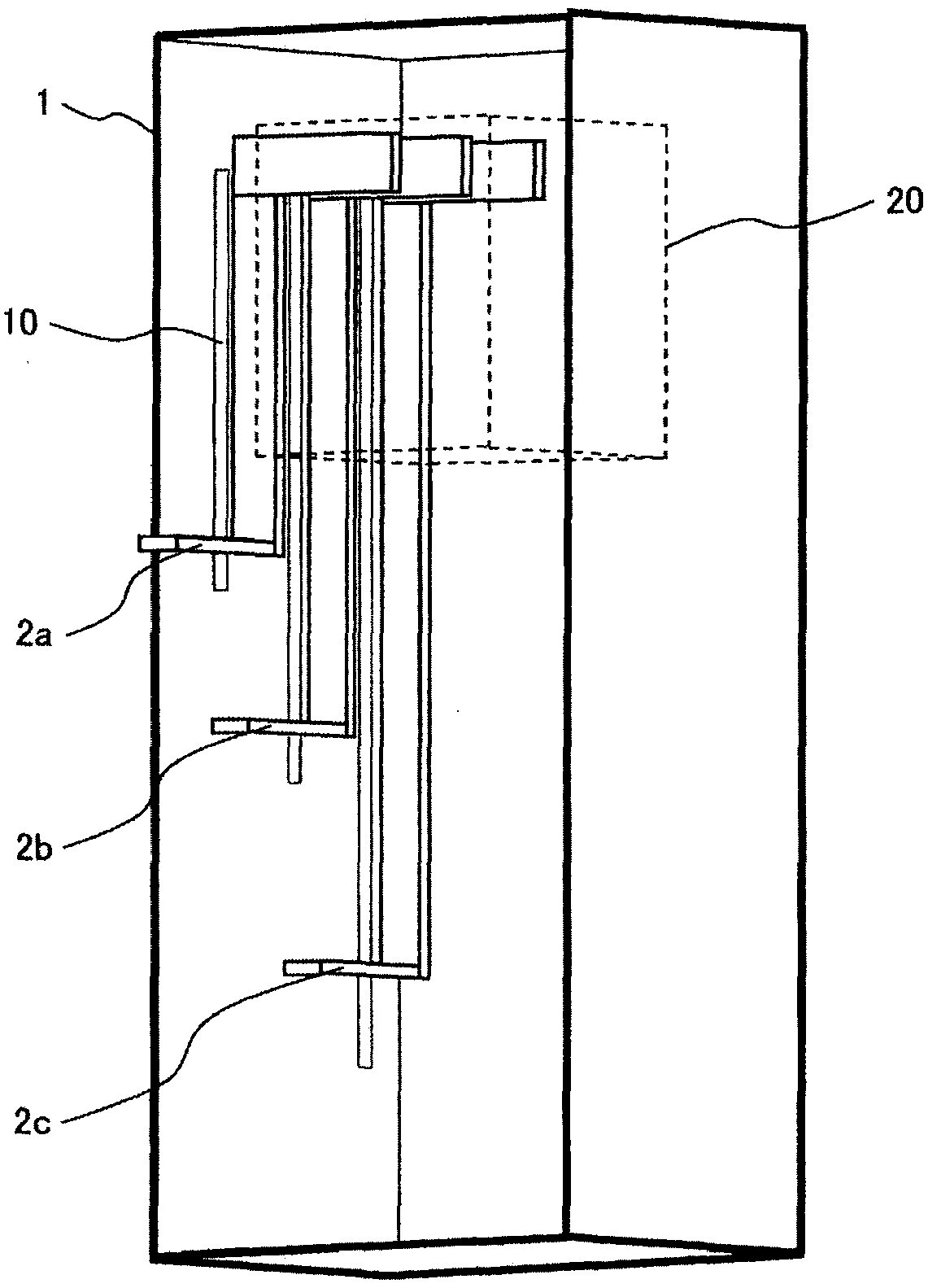
[0051] Figure 2a as well as Figure 2b A schematic configuration of a power conversion device according to Embodiment 1 of the present invention is shown. Figure 2a is a three-dimensional diagram of the internal structure, Figure 2b A plan view showing a frame facing wiring.
[0052] In the first embodiment, the power conversion unit 20 that processes three-phase AC power is accommodated in the casing 1 . In housing 1 , wiring conductor 2 a for U-phase, wiring conductor 2 b for V-phase, and wiring conductor 2 c for W-phase are connected to power conversion unit 20 . Therefore, the output current of the power conversion unit 20 , that is, the three-phase alternating current that is the main current flows through the wiring conductors 2 a , 2 b , and 2 c. The frame body 1 includes a relatively inexpensive steel plate as a metal plate material. The power conversion unit 20 handles large power (for example, several MVA or more). In addition, the frequency of the output cu...
Embodiment 2
[0062] Figure 5a as well as Figure 5b A schematic configuration of a power conversion device according to Embodiment 2 of the present invention is shown. Figure 5a is a perspective view of the internal structure, Figure 5b It shows the side view of the housing 1 seen from the direction in which the wiring conductors 2a, 2b, and 2c are arranged in parallel. Next, differences from Embodiment 1 will be described.
[0063] In Example 2, each slit 10 facing wiring conductors 2a, 2b, and 2c is divided into a plurality along the height direction, and eaves 11 are provided for each divided slit. By providing the eaves 11, it is possible to prevent foreign matter such as dust from entering the housing from the outside.
[0064] like Figure 5a As shown, a part 1a of the frame is interposed between the divided slits. like Figure 5b As shown, one end of the thin plate material constituting the eaves 11 is fixed to the outer surface of a part 1a of the frame body, and the thin...
Embodiment 3
[0067] Image 6 The schematic structure of the power conversion apparatus which is Example 3 of this invention is shown. Book Image 6 It is an external perspective view when the housing surface provided with the slit 10 is seen from the outside. Hereinafter, differences from Embodiment 1 will be described.
[0068] In the present embodiment 3, on the outside of one surface of the frame body 1 provided with the slit 10, a thin plate-shaped cover 12 is provided to block the slit 10, and the cover 12 is made of non-magnetic metal (for example, aluminum or stainless steel).
[0069] The magnetic flux generated by the three-phase alternating current flowing in the wiring conductors 2a, 2b, and 2c also interlinks with the cover 12, but since the magnetic permeability of the nonmagnetic metal is lower than that of the steel plate material constituting the frame body 1, the Almost no eddy current is generated in the cover 12 of the third embodiment. Therefore, the temperature ri...
PUM
 Abstract
Description
Claims
Application Information
 - R&D
- Intellectual Property
- Life Sciences
- Materials
- Tech Scout
- Unparalleled Data Quality
- Higher Quality Content
- 60% Fewer Hallucinations
Browse by: Latest US Patents, China's latest patents, Technical Efficacy Thesaurus, Application Domain, Technology Topic, Popular Technical Reports.
© 2025 PatSnap. All rights reserved.Legal|Privacy policy|Modern Slavery Act Transparency Statement|Sitemap|About US| Contact US: help@patsnap.com