Check patentability & draft patents in minutes with Patsnap Eureka AI!

Collection tank and corresponding heat exchanger

A heat exchanger and collection box technology, applied in the direction of heat exchanger fixation, heat exchange equipment, heat exchanger shell, etc., can solve problems such as the difficulty of inserting heat exchange tubes into the head, and achieve the effect of reducing pressure drop

Active Publication Date: 2022-05-03
VALEO SYST THERMIQUES
View PDF5 Cites 0 Cited by
  • Summary
  • Abstract
  • Description
  • Claims
  • Application Information

AI Technical Summary

Problems solved by technology

However, this counter-flange is only very slightly flanged, which means in other words that the known counter-flange defines a small inlet taper for the insertion of the heat exchange tubes
Consequently, the inlet taper may not be sufficient to allow easy insertion of the heat exchange tubes, and solutions known from the prior art may present difficulties for inserting the heat exchange tubes into the head

Method used


Image

  • Collection tank and corresponding heat exchanger
  • Collection tank and corresponding heat exchanger
  • Collection tank and corresponding heat exchanger

Examples


Embodiment Construction

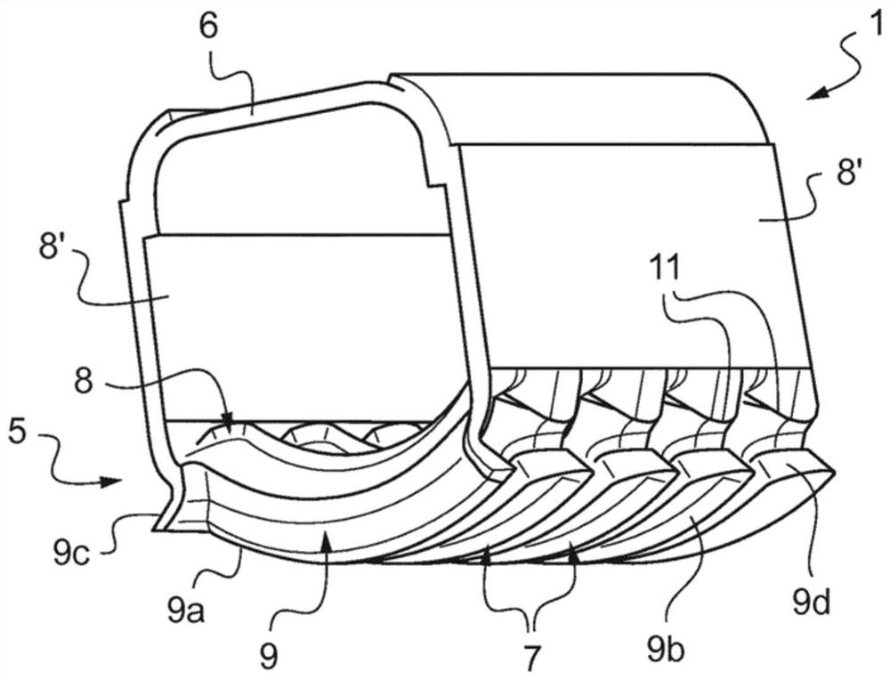
[0045] figure 1 is a simplified schematic diagram showing a fluid collection tank 1 for a heat exchanger (not shown), used in particular in the motor vehicle sector. The heat exchanger can be used in particular as a radiator or as a condenser of a motor vehicle.

[0046] In particular, the invention can be applied to brazed heat exchangers.

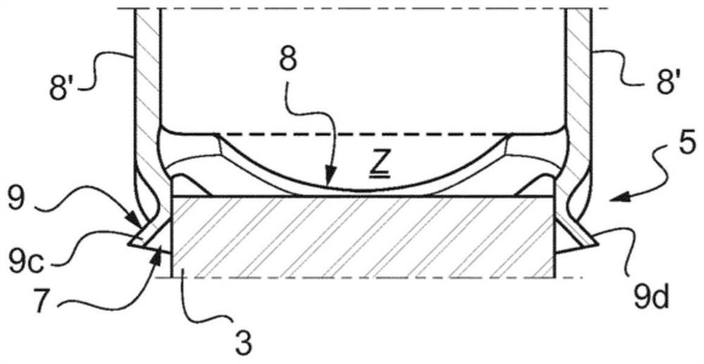
[0047] The heat exchanger comprises a core tube bundle 3 . exist figure 2 , only one end of one tube 3 is visible. The tube 3 is made, for example, of aluminum or an aluminum alloy. These are, for example, approximately flat tubes 3 .

[0048] The collecting tank 1 is configured to receive at least one end of a tube 3 of a heat exchanger, more specifically, the ends of a plurality of tubes 3 in a heat exchanger (not shown). exist figure 2 , only one end of one tube 3 is visible.

[0049] To this end, the collection box 1 comprises a head 5 . The collection box 1 additionally comprises a lid 6 secured to the head 5 to close the ...


PUM


Abstract

The invention relates to a collecting tank (1) for a heat exchanger comprising a head (5) having an at least partially rounded shape, the head comprising: a plurality of openings (7) for the heat exchanger A plurality of heat exchange tubes (3) pass through; and a plurality of flanges (9) surrounding the opening (7). According to the invention, the head (5) comprises a plurality of folds (11), and flanges (9) are formed at the folds (11) of the head (5) and respectively have The roughly flanged shape in the direction of the volume.

Description

technical field [0001] The invention relates to a collecting tank for a heat exchanger, in particular for motor vehicles. The invention also relates to a corresponding heat exchanger. Such heat exchangers are used in particular as radiators for cooling systems, for example in motor vehicles, or in high-pressure applications, for example as condensers for air-conditioning systems. Background technique [0002] In general, such heat exchangers comprise a core tube bundle and at least one collecting tank. This collection box is configured to receive the ends of the tubes of the heat exchanger. [0003] To this end, the collection box generally comprises a head, for example in the form of a head plate. The collection box typically additionally includes a lid secured to the head plate to close the collection box. [0004] The header plate allows the distribution of fluid to the heat exchange tubes, or the collection of fluid from these heat exchange tubes. The head plate is ...

Claims


Application Information

Patent Timeline
Patent Type & Authority Patents(China)
IPC IPC(8): F28F9/02F28F9/04
CPCF28F2280/00F28F9/0224F28F9/0243F28F2225/08F28F9/04F28F1/02F28F2275/00F28F2275/04
Inventor C.里翁德特J-M.勒叙厄尔
Owner VALEO SYST THERMIQUES
Features
  • R&D
  • Intellectual Property
  • Life Sciences
  • Materials
  • Tech Scout
  • Unparalleled Data Quality
  • Higher Quality Content
  • 60% Fewer Hallucinations
Learn More