
Light pipe texturing intensity gradient for electronic devices

A technology of electronic devices and textures, applied in identification devices, display devices, illuminated signs, etc., can solve problems such as clumsy and complicated lamp tube design

Inactive Publication Date: 2017-02-22
THOMSON LICENSING SA
View PDF3 Cites 0 Cited by
  • Summary
  • Abstract
  • Description
  • Claims
  • Application Information

AI Technical Summary

Problems solved by technology

[0007] Because existing methods of trying to achieve varying textures for signs, buttons, and indicators are cumbersome and require complex lamp designs, simple methods of texture control are needed

Method used


Image

  • Light pipe texturing intensity gradient for electronic devices
  • Light pipe texturing intensity gradient for electronic devices
  • Light pipe texturing intensity gradient for electronic devices

Examples


Embodiment Construction

[0022] The principle of the present invention relates to an electronic device having a textured logo, a button, and / or an indicator signal part.

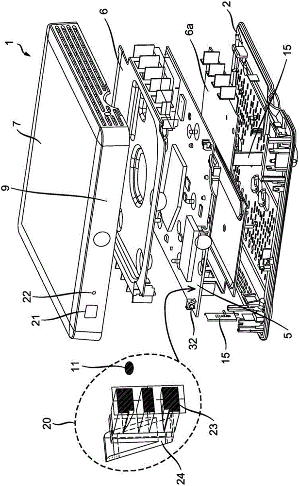
[0023] figure 1 It further shows the electronic device 1 with a logo, button or indicator signal component 20 and how it can be positioned in the electronic device 1. The electronic device 1 may be a set-top box. The assembly 20 includes a backlight 11 and a lamp tube 23. The front surface 24 of the lamp tube 23 is positioned at the hole 21 in the front wall of the device 1. There may also be an additional light indicator 22, which may be a "record" light. figure 1 It is shown that the component 20 can be positioned near or above the printed circuit board (pcb) 5. The backlight 11 can be positioned on the pcb5 and behind the lamp tube 23 and the front wall 9. The electronic device 1 may include a flange, which may have a circumferential portion or a planar circumferential portion, which defines the shape of a hole 21 through which th...


PUM


Abstract

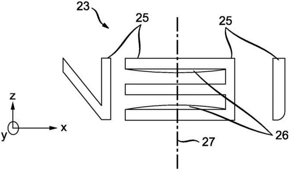
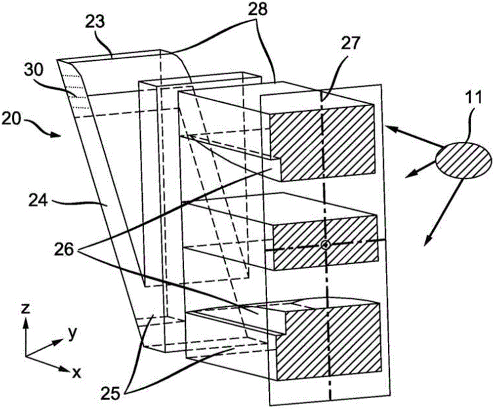
The invention is an illumination system for a logo (20) on the front of an electronic device (1) such as a set top box. The logo (20) is part of a light pipe (23) and the logo (20) is illuminated by projecting light on the front surface (24) of the light pipe (23). The front surface (24) is textured or tinted to evenly distribute the light to a viewer. The light source (11) for illuminating the logo (20) is positioned at an entrance end of the light pipe (23) as shown in the figure. The shape of the light pipe (23) is substantially uniform throughout the length of the light pipe (23) and the shape is substantially the shape of the logo (20). The light pipe (23) can have a cut away region near the front surface to create localized lighting contrasts.

Description

[0001] Cross references to related applications [0002] This application claims the priority of European application 14305381.7 filed on March 18, 2014. Technical field [0003] The principles of the present invention generally relate to electronic devices, and more specifically to electronic devices having light tubes for illuminating signs. Background technique [0004] Many manufacturers and customers prefer electronic devices with logos, buttons, and indicating signals, which can be illuminated so that the product can be identified, the active buttons on the product can be identified, and the status of the device can be visualized by the signal Pass it to the user. However, this feature of lighting adds cost to the device and requires some extra space in the device to be dedicated to supporting lighting. [0005] In addition, some manufacturers require and / or desire that these features (ie logos, buttons, and indication signals) have aesthetic and pleasing visual effects to mak...

Claims


Application Information

Patent Timeline
IPC IPC(8): G09F9/305G09F13/04G09F23/00
CPCG09F9/305G09F13/04G09F23/0058G09F13/0427G02B6/0001
Inventor C.M.W.普罗克特V.马利特
Owner THOMSON LICENSING SA
Learn More