Supercharge Your Innovation With Domain-Expert AI Agents!

Method and device for controlling signal transmission during data rate change

A data rate and control signal technology, applied in the field of signal transmission, can solve problems such as fluctuations

Inactive Publication Date: 2019-11-05
ALCATEL LUCENT SAS
View PDF3 Cites 0 Cited by
  • Summary
  • Abstract
  • Description
  • Claims
  • Application Information

AI Technical Summary

Problems solved by technology

[0005] Therefore, during the transition phase, i.e., before convergence is reached, BER performance may degrade and may fluctuate, but there is no known solution for overcoming these drawbacks

Method used


Image

  • Method and device for controlling signal transmission during data rate change
  • Method and device for controlling signal transmission during data rate change
  • Method and device for controlling signal transmission during data rate change

Examples


Embodiment Construction

[0027] In the following, in particular a method for controlling the transmission of a signal between the transmitter 2 and the receiver 3 during a phase of changing the data rate of the signal is disclosed.

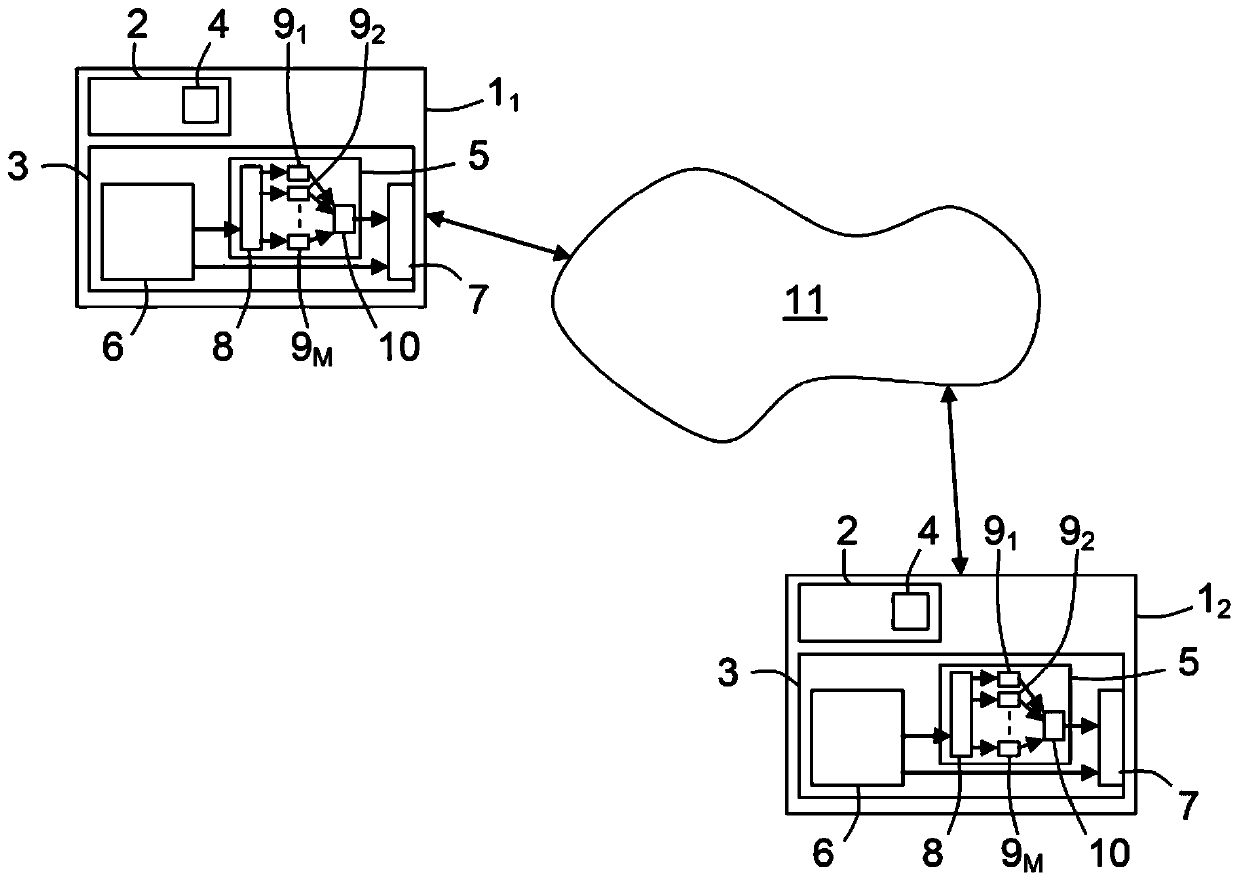
[0028] In the description below, and as figure 1 As illustrated in , it should be considered that the transmitter 2 and the receiver 3 involved in the signal transmission are respectively equipped with a first 1 connected to a communication network 11 (regardless of its type (wired or wireless)). 1 and the second 1 2 transceiver. But they could be part of any other type of electronic device that provides two-way or one-way communication functionality.

[0029] Therefore, and if figure 1 illustrated in, each transceiver 1 i (i=1 or 2) includes transmitter 2 and receiver 3 .

[0030] Each transmitter 2 includes a DSP software block (not shown) arranged to generate a signal having a selected modulation format, a selected coding rate, and a selected symbol rate, and capa...


PUM


Abstract

A method is intended for controlling transmission of a signal between a transmitter (2) and a receiver (3) during a phase of change of signal data rate. This method consists, when this change is requested: - in informing these transmitter (2) and receiver (3) of a start of a transition phase, then - in retransmitting this signal N times, with N ‰¥ 1, in identical signal parts having a chosen length, and in storing these N retransmitted identical signal parts successively received by the receiver (3) to combine them together to produce a combined signal part, and to temporarily output these combined signal parts with an auxiliary data rate depending on N and on this signal part length, then - in informing the transmitter (2) and receiver (3) of the end of the transition phase when the signal data rate change is finished.

Description

technical field [0001] The present invention relates to the transmission of signals via a communication network, and more precisely to the change of the signal data rate during signal transmission. Background technique [0002] Previous generation transceivers (ie, communication devices including transmitters and receivers) were able to support multiple data rates by changing the modulation format, or the coding rate or symbol rate of the signal. This allows the transceiver to switch from one data rate to another, not only between two signal transmissions or receptions, but also during signal transmission or reception. [0003] It is known to those skilled in the art that the latter case requires that the transceiver be able to adapt itself on the fly without losing any signal data, which means that the BER (Bit Error Rate) must be maintained below a given threshold. Such adaptation requires updates to some of the digital signal processing (or DSP) software blocks in the re...

Claims


Application Information

Patent Timeline
Patent Type & Authority Patents(China)
IPC IPC(8): H04L1/00
CPCH04L1/0002H04L1/08H04B1/02H04B1/06
Inventor P·拉耶克
Owner ALCATEL LUCENT SAS
Features
  • R&D
  • Intellectual Property
  • Life Sciences
  • Materials
  • Tech Scout
  • Unparalleled Data Quality
  • Higher Quality Content
  • 60% Fewer Hallucinations
Learn More