Check patentability & draft patents in minutes with Patsnap Eureka AI!

Opposed combustion boiler and flue gas recirculation combustion system using the boiler

A technology for hedging combustion and combustion systems, applied in the field of boilers, can solve the problems of thinning of water wall tubes, high temperature corrosion, hazards of safe and economical operation of boilers, etc., and achieve the effects of isolating contact, improving atmosphere, and preventing high temperature corrosion.

Active Publication Date: 2020-02-11
DONGFANG BOILER GROUP OF DONGFANG ELECTRIC CORP
View PDF6 Cites 0 Cited by
  • Summary
  • Abstract
  • Description
  • Claims
  • Application Information

AI Technical Summary

Problems solved by technology

Due to the weak flue gas mixing along the furnace width direction, it is difficult to supplement the air close to the surface of the side wall, especially near the middle of the side wall (along the depth direction of the furnace), the lack of wind is particularly obvious, resulting in the flue gas of the front and rear walls facing the combustion boiler close to the surface of the side wall The oxygen content in the furnace is very low, the carbon monoxide content is high, and the high-temperature flue gas is a strong reducing atmosphere. In addition, the parameters of the current boiler are getting higher and higher, and the temperature of the furnace water wall is also getting higher and higher, and the water wall of the side wall is easy to appear. High-temperature corrosion, high-temperature corrosion causes the wall of the water-cooled wall to thin, which brings great harm to the safe and economical operation of the boiler

Method used


Image

  • Opposed combustion boiler and flue gas recirculation combustion system using the boiler
  • Opposed combustion boiler and flue gas recirculation combustion system using the boiler
  • Opposed combustion boiler and flue gas recirculation combustion system using the boiler

Examples


Embodiment Construction

[0019] The present invention will be further described in detail below in conjunction with specific examples, but the implementation of the present invention is not limited thereto.

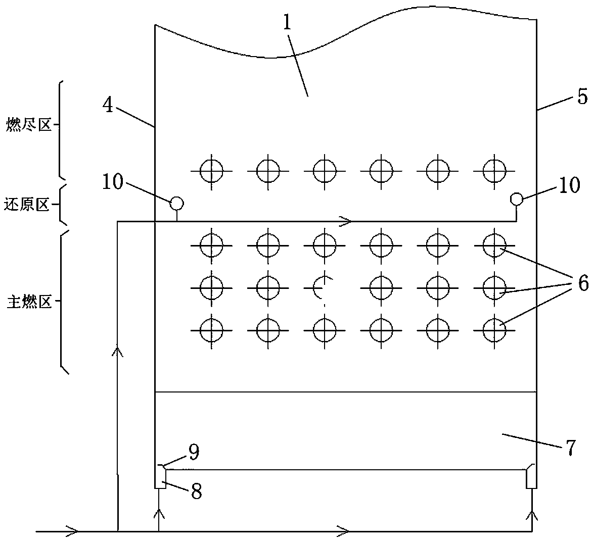
[0020] Such as figure 1 and figure 2 As shown, the opposed combustion boiler of the present invention includes a furnace 1, and the furnace 1 is surrounded by a front wall 2, a rear wall 3, a left wall 4 and a right wall 5. The furnace 1 includes a main combustion zone, a reduction zone and a burnout zone from low to high. Both the front wall 2 and the rear wall 3 are provided with burner nozzles 6 (located in the main combustion zone) and burnout air nozzles 14 (located in the burnout zone). The bottom of the furnace 1 has a cold ash hopper 7, and the bottom of the cold ash hopper 7 is provided with two flue gas inlets 8, which are respectively arranged on the bottom of the cold ash hopper 7 under the left wall 4 and the right side wall 5. The gas inlets 8 are respectively used to introduce ...


PUM


Abstract

The invention relates to the field of boilers, and discloses an opposed firing boiler which comprises a hearth (1); the hearth (1) is enclosed by front and rear walls (2,3) and two side walls (4,5); the front and rear walls (2, 3) are equipped with combustor spray holes (6); the hearth (1) comprises a primary combustion region, a reducing region and a complete-combustion region from low to high; a cold ash hopper (7) is arranged on the bottom of the hearth (1); a flue gas inlet (8) is formed in the cold ash hopper (7); and the flue gas inlet (8) is used for introducing flue gas which upwards flows in a direction close to the inner walls of the side walls (4,5). According to the opposed firing boiler disclosed by the invention, a protective layer is formed by introducing flue gas which is introduced from the inner walls of the side walls and flows from bottom to top, so that atmosphere in side wall areas of the opposed firing boiler is improved and cannot be improved by other existing closing-to-wall air means, and therefore, contact between strong reducing atmosphere and a water-cooling wall is effectively isolated, and therefore, high-temperature corrosion of side walls can be prevented.

Description

technical field [0001] The invention relates to the technical field of boilers, in particular to a counter-combustion boiler for preventing high-temperature corrosion of side walls and a flue gas recirculation combustion system using the counter-combustion boiler. Background technique [0002] With the application of air staged combustion technology, the front and rear wall opposed combustion boilers have brought many negative effects while reducing NOx, among which high temperature corrosion is one of them. Due to the weak flue gas mixing along the furnace width direction, it is difficult to supplement the air close to the surface of the side wall, especially near the middle of the side wall (along the depth direction of the furnace), the lack of air is particularly obvious, resulting in the flue gas of the front and rear walls facing the combustion boiler close to the side wall surface The oxygen content in the furnace is very low, the carbon monoxide content is high, and ...

Claims


Application Information

Patent Timeline
Patent Type & Authority Patents(China)
IPC IPC(8): F23C9/00
CPCF23C9/003F23C2201/101F23C2900/09002
Inventor 吉彦鹏张定海朱骅莫春鸿
Owner DONGFANG BOILER GROUP OF DONGFANG ELECTRIC CORP
Features
  • R&D
  • Intellectual Property
  • Life Sciences
  • Materials
  • Tech Scout
  • Unparalleled Data Quality
  • Higher Quality Content
  • 60% Fewer Hallucinations
Learn More