
Infrared receiving circuit

An infrared receiving and circuit technology, applied in the field of communication, can solve the problems of infrared receiving signal light-emitting diode dark current influence, unfavorable system integration, etc., and achieve the effects of reducing circuit manufacturing costs, accurate signals, and easy integration

Active Publication Date: 2017-03-15
上海胤祺集成电路有限公司 +1
View PDF12 Cites 1 Cited by
  • Summary
  • Abstract
  • Description
  • Claims
  • Application Information

AI Technical Summary

Problems solved by technology

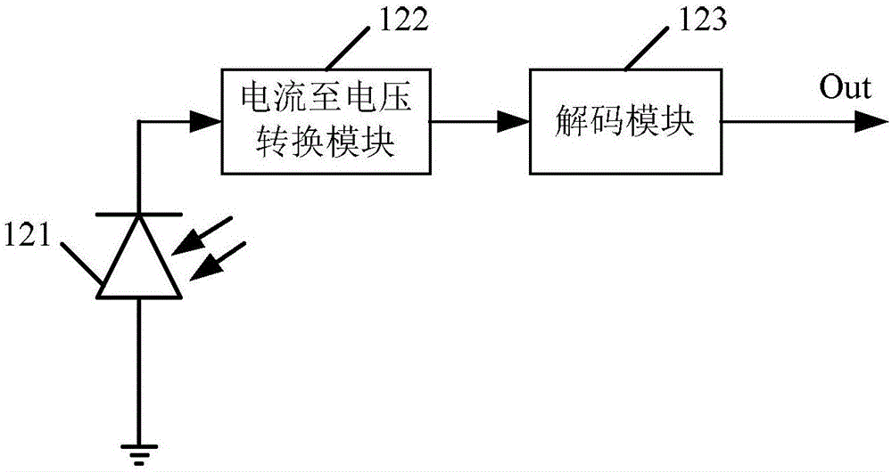
[0006] Traditional infrared receiving circuits such as Figure 1b The circuits in it are all packaged on an independent chip, which is not conducive to system integration, and the infrared receiving signal is easily affected by the dark current of the light-emitting diode, and the accuracy needs to be further improved

Method used


Image

  • Infrared receiving circuit
  • Infrared receiving circuit
  • Infrared receiving circuit

Examples


Embodiment Construction

[0026] The specific implementation of the infrared receiving circuit provided by the present invention will be described in detail below in conjunction with the accompanying drawings.

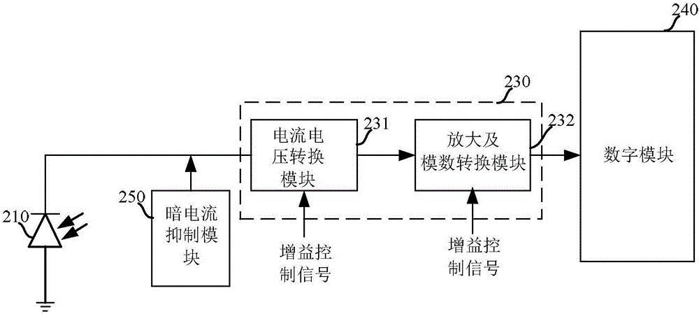
[0027] Please refer to figure 2 , is a schematic diagram of a module structure of an infrared structure circuit according to a specific embodiment of the present invention.

[0028] The infrared receiving circuit includes: a photodiode 210 , a main receiving module 230 , a dark current suppression module 250 and a digital module 240 .

[0029] The photodiode 210 is used to receive an infrared signal, such as infrared light sent by an infrared remote controller, and generate a current signal.

[0030] Since the photodiode 210 also generates current for light signals such as natural light (sunlight) and fluorescent lamps when receiving infrared light signals, this part of the current is called dark current. This part of the current changes slowly and is a low-frequency signal, which will be pa...


PUM


Abstract

The invention provides an infrared receiving circuit. The infrared receiving circuit comprises a photodiode, a dark current inhibition module and a main receiving module, wherein the dark current inhibition module is connected with a current output end of the photodiode and is used for removing dark current in an output current signal of the photodiode; the main receiving module is connected with the photodiode and the dark current inhibition module and is used for converting an effective current signal which is output by the photodiode and has no dark current into a voltage signal and is used for carrying out analog-to-digital conversion on the voltage signal to form a digital signal and outputting the digital signal. According to the infrared receiving circuit provided by the invention, influences of the dark current are avoided and the accuracy of receiving the signal is improved.

Description

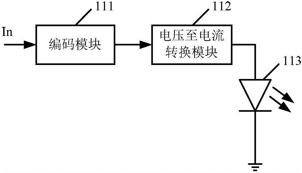
technical field [0001] The invention relates to the communication field, in particular to an infrared receiving circuit. Background technique [0002] At present, infrared remote controllers have become standard components of household appliances. Almost all functions of televisions, VCRs, DVDs, audio power amplifiers, air conditioners, and infrared meter reading devices in the State Grid can be controlled by infrared remote controls. [0003] Figure 1a is the equivalent diagram of the infrared sending circuit, Figure 1b It is the equivalent diagram of the infrared receiving circuit. [0004] Figure 1a Among them, the input signal In is encoded by the encoding module 111, and then the voltage signal is converted into a current signal by the voltage-to-current conversion module 112, so that the light-emitting diode 113 emits infrared light. [0005] Figure 1b Among them, after the photodiode 121 receives the infrared light, it generates a current signal, which is conv...

Claims


Application Information

Patent Timeline
Patent Type & Authority Applications(China)
IPC IPC(8): G08C23/04
CPCG08C23/04Y02D30/70
Inventor 夏建宝
Owner 上海胤祺集成电路有限公司
Learn More