
Multimode Power Management System

A power management system, multi-mode technology, applied in control/regulation systems, electrical components, regulating electrical variables, etc., can solve the problems of high risk, long verification period, and limited application scope of the power management system, and achieve no stability. problems, improve the development success rate, and save development time

Active Publication Date: 2019-10-11
HUNAN GOKE MICROELECTRONICS
View PDF13 Cites 0 Cited by
  • Summary
  • Abstract
  • Description
  • Claims
  • Application Information

AI Technical Summary

Problems solved by technology

When the application conditions of the analog switching power supply change or need to be transferred to a new process, a new feedback loop needs to be redesigned, and the verification cycle is relatively long; moreover, the feedback loop may be unstable in the new design and new process, making power management The system risk is relatively large, which affects the rapid entry of products into the market
[0004] If the power management system in the SOC chip of the prior art uses a digital switching power supply, although the digital switching power supply can better adapt to different applications and process requirements, the switching bandwidth of the pure digital switching power supply is relatively low, and the fast load changes make the power supply The ripple is large, so its applicable range is relatively limited
On the other hand, switching power supply noise may also affect other sensitive circuits of the SOC chip, and the efficiency will drop when the input voltage is low

Method used


Image

  • Multimode Power Management System
  • Multimode Power Management System
  • Multimode Power Management System

Examples


Embodiment Construction

[0042] The technical solutions in the embodiments of the present invention will be described clearly and completely below. Obviously, the described embodiments are only a part of the embodiments of the present invention, rather than all the embodiments. Based on the embodiments of the present invention, all other embodiments obtained by those of ordinary skill in the art without creative work shall fall within the protection scope of the present invention.

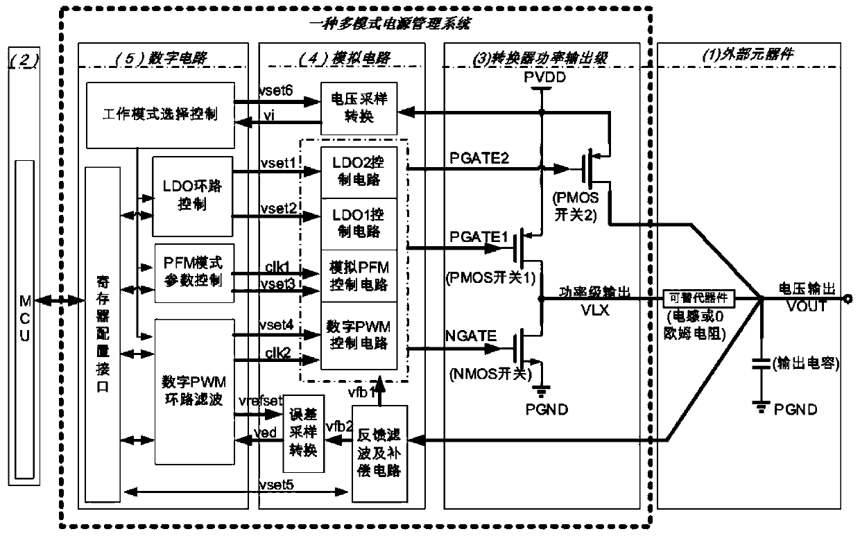
[0043] To solve the problems in the prior art, the present invention provides a multi-mode power management system suitable for SOC chips. The multi-mode power management system has the following characteristics:

[0044] (1) Using a flexible digital circuit to control the power management system in analog PFM (Pulse Frequency Modulation, pulse frequency modulation) switch output, digital PWM (Pulse Width Modulation, pulse width modulation) switch output, switching power supply topology LDO (Low Dropout Regulator, low voltage ...


PUM


Abstract

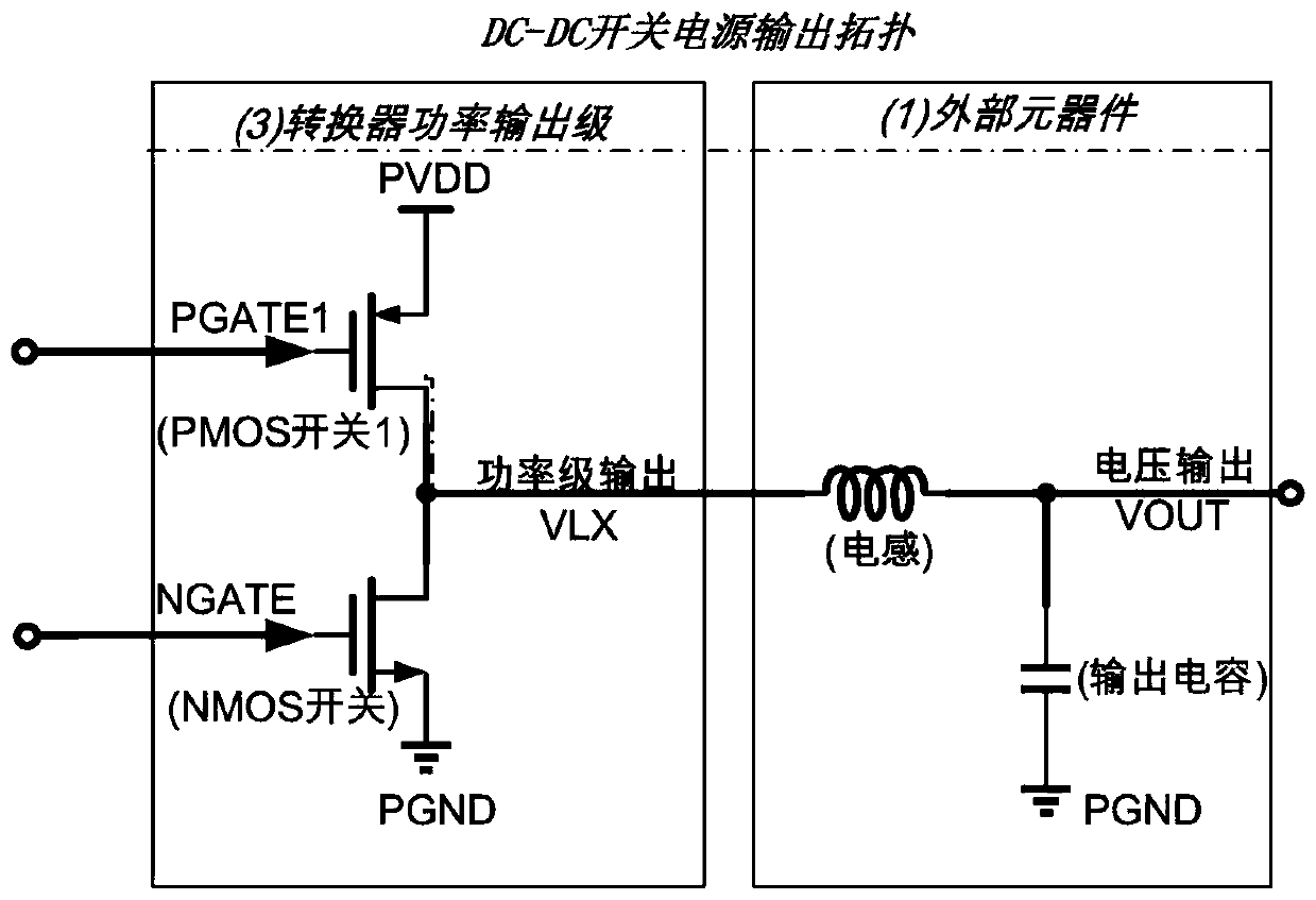
The invention provides a multi-mode power management system suitable for SOC chips. The multi-mode power management system includes a digital circuit, an analog circuit and a converter output stage, wherein the analog circuit is connected to the digital circuit, and it includes an analog PFM control circuit, a digital PWM control circuit, a first LDO control circuit and The second LDO control circuit; the analog PFM control circuit, the digital PWM control circuit, the first LDO control circuit and the second LDO control circuit form an output drive unit for providing an output drive signal to the power output stage of the converter, so The output driving signal is used to drive the power output stage of the converter to respectively realize analog PFM switching power supply output mode, digital PWM switching power supply output mode, switching power supply topology LDO output mode and voltage output in LDO output mode.

Description

【Technical Field】 [0001] The present invention relates to power supply technology, and in particular, to a multi-mode power management system suitable for SOC (System on a chip) chips. 【Background technique】 [0002] As we all know, SOC chips usually need to use a power management system to provide stable power to the internal circuits of the chip. [0003] The power management system in the prior art generally uses an analog switching power supply or a digital switching power supply. When the application conditions change or the analog switching power supply needs to be transferred to a new process, a new feedback loop needs to be redesigned, and the verification period is relatively long; and the feedback loop is unstable in the new design and new process, which makes the power management The system risk is relatively high, which affects the product to enter the market quickly. [0004] If the power management system in the prior art SOC chip uses a digital switching power supply...

Claims


Application Information

Patent Timeline
Patent Type & Authority Patents(China)
IPC IPC(8): H02M3/158
Inventor 汪坚雄姜黎李天望万鹏袁涛
Owner HUNAN GOKE MICROELECTRONICS
Learn More