Automatic screw assembling machine

A technology of assembly machine and screw machine, which is applied in the direction of metal processing, metal processing equipment, manufacturing tools, etc., can solve the problems of high labor intensity, high noise of the vibrating plate, and large manufacturing error of the supply channel, so as to shorten the transportation time and reduce the noise. Small size and improved assembly efficiency

Inactive Publication Date: 2017-05-10
CHANGSHA RUIBOTE TECHNOLGOY CO LTD
View PDF7 Cites 5 Cited by
  • Summary
  • Abstract
  • Description
  • Claims
  • Application Information

AI Technical Summary

Problems solved by technology

[0003] During the automatic conveying and assembly of screws, the sorting of the screws generally adopts a vibrating style, and the manufacturing error of the supply channel of the screws is large, which is prone to material jams, and the automatic feeding of the screws cannot be achieved smoothly, and the vibration plate is noisy, which affects the environment.
The existing process of automatic delivery of assembly scr

Method used


Image

  • Automatic screw assembling machine
  • Automatic screw assembling machine

Examples


Example Embodiment

[0017] In order to facilitate the understanding of the present invention, the present invention will be described more comprehensively and in detail below with reference to the accompanying drawings and preferred embodiments of the specification, but the protection scope of the present invention is not limited to the following specific embodiments.

[0018] Unless otherwise defined, all technical terms used hereinafter have the same meaning as commonly understood by those skilled in the art. The technical terms used herein are only for the purpose of describing specific embodiments, and are not intended to limit the protection scope of the present invention.

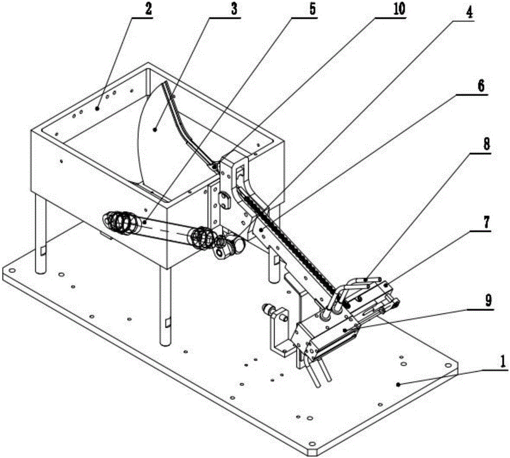
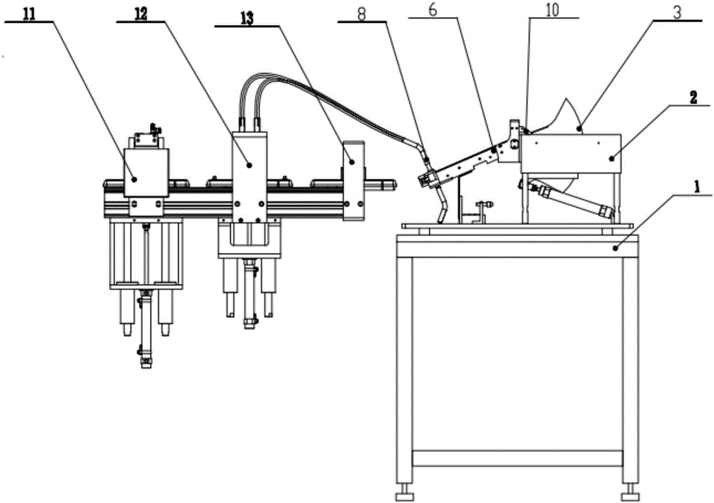
[0019] figure 1 , a screw assembly machine, comprising a base frame 1, a hopper 2 is arranged on the upper part of the base frame 1, the bottom of the hopper 1 is provided with a trough-type feeding plate 3, and the hopper 2 and the base frame 1 are arranged obliquely There is a telescopic cylinder 5, one end of the tel...


PUM


Abstract

The invention discloses an automatic screw assembling machine which comprises a chassis. A hopper is arranged at the upper portion of the chassis, a groove type feeding plate is arranged at the bottom of the hopper, a stretchable air cylinder is arranged between the hopper and the chassis in an inclined manner, one end of the stretchable air cylinder is connected to the chassis, and the other end of the stretchable air cylinder is connected with the lower end of the groove type feeding plate through a rocker; a bridge plate is arranged at a discharging opening of the hopper and provided with a groove, a sliding block with a containing groove is arranged at an outlet of the bridge plate, a feeding air pipe is connected to the sliding block, and a pushing air cylinder for conveying screws to the feeding air pipe is arranged on the sliding block in the length direction; and a screwing machine with a tray clamp is arranged at an outlet of the feeding air pipe. By means of the automatic screw assembling machine, the screws can be automatically conveyed to the tray clamp, residual screws flowing into the tray clamp can be removed, and whether the screws are assembled in place or not can be detected in time.

Description

technical field [0001] The invention particularly relates to a screw supply and conveying device used in the product assembly process, in particular to an automatic screw assembly machine. Background technique [0002] Screws are commonly used fasteners, and for complex parts with many connection parts, the number of screws used is also relatively large. At present, during the screw assembly process, the screw is usually loaded manually. When the operator needs to use a screw, he takes out a screw from a pile of screws, then adjusts the position of the screw and installs it in the corresponding hole. superior. [0003] During the automatic conveying and assembly of screws, the sorting of the screws generally adopts a vibrating style. The manufacturing error of the screw supply channel is large, and it is easy to cause material jams. The automatic feeding of the screws cannot be achieved smoothly, and the vibration plate is noisy, which affects the environment. The existing...

Claims


Application Information

Patent Timeline
IPC IPC(8): B23P19/06B23P19/00
CPCB23P19/06B23P19/005
Inventor 李峰陈思颖
Owner CHANGSHA RUIBOTE TECHNOLGOY CO LTD
Why Eureka
Try Eureka