Check patentability & draft patents in minutes with Patsnap Eureka AI!

Power Rotary Eccentric Tool Holder and Power Head Device

A technology of power rotation and tool seat, which is applied in the direction of driving devices, positioning devices, manufacturing tools, etc., can solve problems such as low efficiency, achieve great interchangeability, and reduce equipment investment costs

Active Publication Date: 2018-07-10
深圳市硕方精密机械有限公司
View PDF5 Cites 0 Cited by
  • Summary
  • Abstract
  • Description
  • Claims
  • Application Information

AI Technical Summary

Problems solved by technology

At present, the processing of U-shaped bone screws needs to be processed through multiple processes and multiple equipments. There is no tool holder specially used for processing U-shaped bone screws, which is inefficient.

Method used


Image

  • Power Rotary Eccentric Tool Holder and Power Head Device
  • Power Rotary Eccentric Tool Holder and Power Head Device

Examples


Embodiment Construction

[0021] In order to have a clearer understanding of the technical features, purposes and effects of the present invention, the specific implementation manners of the present invention will now be described in detail with reference to the accompanying drawings.

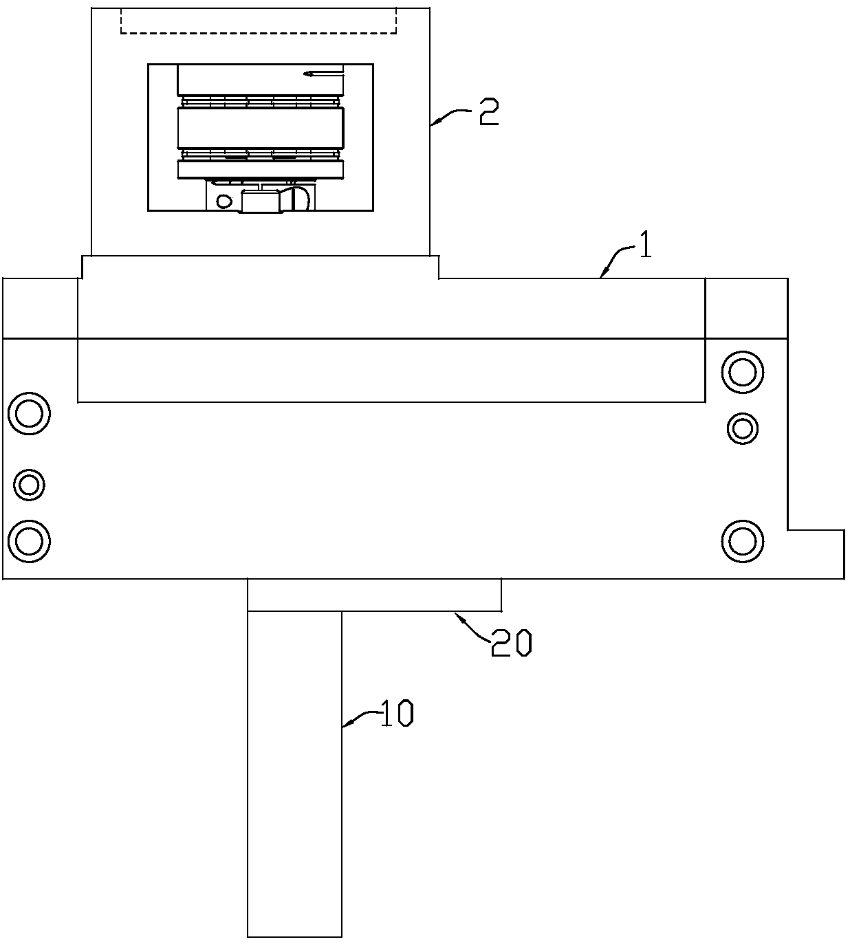
[0022] Such as figure 1 As shown, the power rotating eccentric tool seat of an embodiment of the present invention can be used for U-shaped bone nail processing, and it includes a seat body 10, a rotating disc 20 mounted on the seat body 10 rotatably relative to the seat body 10, and a rotating disk 20 installed on the seat body The transmission assembly 30 on 10, at least one ER chuck assembly 40 installed on the base 10. The transmission assembly 30 and the rotating disc 20 are located on the same end face of the base body 10 , and the ER chuck assembly 40 is located on the side surface of the base body 10 and is in transmission connection with the transmission assembly 30 .

[0023] The entire power rotating eccentr...


PUM


Abstract

The invention discloses a power rotary eccentric cutter base and a power head device. The power rotary eccentric cutter base comprises a base body, a rotary plate which is opposite to the base body and rotationally installed on the base body, a transmission assembly installed on the base body, and at least one ER chuck assembly installed on the base body. The transmission assembly and the rotary plate are located on the same end face of the base body, and the ER chuck assembly is located on the side face of the base body and in transmission connection with the transmission assembly. Proper machining angles can be selected according to different machining requirements, and the cutter base is used for machining U-shaped bone nail parts and can efficiently meet machining and manufacturing requirements of the parts at a time. The cutter base meets most machining requirements, a 90-degree angle can be selected, oblique machining can also be conducted, end face milling can be conducted at 0 degree, lateral face milling can be conducted at 90 degrees, the cutter base is multifunctional, the equipment investment cost is reduced, and interchangeability is very high.

Description

technical field [0001] The invention relates to a power rotating eccentric tool seat, in particular to a power rotating eccentric tool seat and a power head device for processing U-shaped bone nails. Background technique [0002] Bone nails are widely used in the medical industry, and U-shaped bone nails are a special type of part in bone nails, which play a very important role in the treatment of metacarpal and head fractures. At present, the processing of U-shaped bone screws needs to be processed through multiple processes and multiple equipments, and there is no tool holder specially used for processing U-shaped bone screws, which is inefficient. Contents of the invention [0003] The technical problem to be solved by the present invention is to provide a power rotating eccentric tool holder for processing U-shaped bone nails and a power head device with the eccentric tool holder. [0004] The technical solution adopted by the present invention to solve the technical ...

Claims


Application Information

Patent Timeline
Patent Type & Authority Patents(China)
IPC IPC(8): B23Q3/00B23Q5/02B23Q5/04B23Q5/10
CPCB23Q3/00B23Q5/02B23Q5/04B23Q5/10
Inventor 缪旭东
Owner 深圳市硕方精密机械有限公司
Features
  • R&D
  • Intellectual Property
  • Life Sciences
  • Materials
  • Tech Scout
  • Unparalleled Data Quality
  • Higher Quality Content
  • 60% Fewer Hallucinations
Learn More