A Transversely Asymmetric Reflectionless Periodic Waveguide Microcavity Bandpass Filter
A technology of band-pass filter and periodic wave, applied in the direction of optical waveguide light guide, instrument, light guide, etc., can solve the problems of increasing system complexity and chip area, reducing production cost, unfavorable scale integration application, etc., and achieves compact size and structure Simple, size-reducing effect
- Summary
- Abstract
- Description
- Claims
- Application Information
AI Technical Summary
Problems solved by technology
Method used
Image

Examples
Embodiment 1
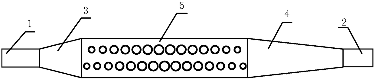
[0035] Below to figure 1 A specific implementation structure shown is illustrated by taking a silicon-on-insulator (Silicon on Silica) substrate widely used in silicon photonics technology as an example, and the thickness of silicon on the top layer of the substrate is 220nm.
[0036] The resonant frequency is calculated by the plane wave expansion method and the fabrication parameters of the device are determined. like figure 1 As shown, the periodic unit adopts an asymmetric double circular hole structure, that is, the horizontal positions of the upper and lower rows of small holes are staggered by half a period, so that the periodic waveguide unit is laterally asymmetric. At the same time, in order to design the resonant frequency of the microcavity at the edge of the second energy band, a small hole with a larger radius is used in the center of the microcavity, and the radius of the circular hole is gradually reduced to both sides of the microcavity. The resonance mode ...
Embodiment 2
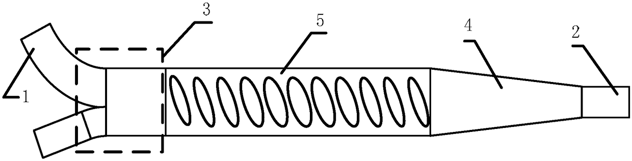
[0043] like figure 2 Shown is another embodiment in which the periodic unit adopts a single row of inclined ellipses and the high-order mode attenuator adopts asymmetrical Y bifurcations. The major axis of the ellipse forms a certain negative angle with the vertical direction to form a transverse asymmetric structure. After determining the periodic unit corresponding to the resonant frequency during design, optimize the waveguide width so that the propagation constant of the high-order mode of the reflected wave is the same as that of the other waveguide except the input port waveguide of the asymmetric Y bifurcation, so that the reflected wave can be coupled to the waveguide And completely lossy, achieving no reflection at input port 1.
Embodiment 3
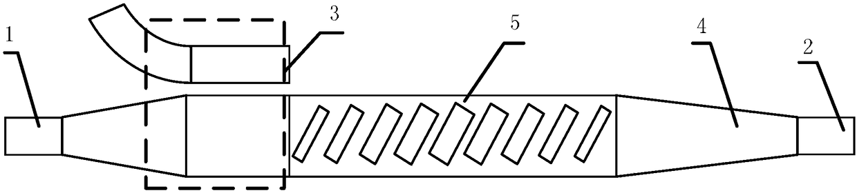
[0045] like image 3 Shown is an embodiment in which the periodic unit is a single row of oblique rectangular holes, and the high-order mode attenuator uses a directional coupler. In this embodiment, the long side of the rectangle forms a positive angle with the vertical direction to form a laterally asymmetric structure, and the propagation constant of the reflected high-order mode is similar to that of the waveguide on the other side of the directional coupler, so the reflected wave is coupled to the waveguide on the other side and lost, realizing Similar to Embodiment 1 and Embodiment 2, the effect of eliminating the reflection of input port 1 is achieved.
PUM
 Abstract
Description
Claims
Application Information
 - R&D
- Intellectual Property
- Life Sciences
- Materials
- Tech Scout
- Unparalleled Data Quality
- Higher Quality Content
- 60% Fewer Hallucinations
Browse by: Latest US Patents, China's latest patents, Technical Efficacy Thesaurus, Application Domain, Technology Topic, Popular Technical Reports.
© 2025 PatSnap. All rights reserved.Legal|Privacy policy|Modern Slavery Act Transparency Statement|Sitemap|About US| Contact US: help@patsnap.com