Elevator control system and elevator door lock bypass device control panel
A technology of bypass device and control panel, which is applied in the direction of transportation and packaging, elevators and elevators in buildings, etc., which can solve the problems of untimely removal of the short circuit wiring of the door safety circuit and safety risks.
Active Publication Date: 2017-05-24
XJ SCHINDLER XUCHANG ELEVATOR
10 Cites 0 Cited by
AI-Extracted Technical Summary
Problems solved by technology
[0006] The purpose of the present invention is to provide an elevator control system and an elevator door lock bypass device control panel t...
Method used
Further preferably, realize elevator door lock bypass device control board by relay, connect each switch ...
Abstract
The invention discloses an elevator control system and an elevator door lock bypass device control panel. The control panel comprises a first interface, a second interface, a third interface, a fourth interface, a fifth interface, a first branch circuit, a second branch circuit, a third branch circuit and a fourth branch circuit, wherein the first interface is used for being connected with a first node in a door safety circuit, the second interface is used for being connected with a second node in the door safety circuit, the third interface is used for being connected with a third node in the door safety circuit, the fourth interface is used for being connected with a fourth node in the door safety circuit, the fifth interface is used for being connected with a fifth node in the door safety circuit, the first branch circuit is connected between the first interface and the second interface, the second branch circuit is connected between the first interface and the third interface, the third branch circuit is connected between the third interface and the fourth interface, and the fourth branch circuit is connected between the fourth interface and the fifth interface; and no switch exists between the first node and the second node, an elevator door lock switch is arranged between the second node and the third node, no switch exists between the third node and the fourth node, and door lock switches, connected with one another in series, of all layers are arranged between the fourth node and the fifth node. By means of the elevator control system and the elevator door lock bypass device control panel, safety accidents caused by untimely disassembling of short-link wires of the short-link door safety circuit can be avoided.
Application Domain
ElevatorsBuilding lifts
Technology Topic
Control systemElevator control system
Image
Examples
- Experimental program(1)
Example Embodiment
[0021] The present invention will be further described below with reference to the drawings and embodiments. However, the use and purpose of these exemplary embodiments are only to illustrate the present invention, and do not constitute any limitation on the actual protection scope of the present invention in any form, let alone limit the protection scope of the present invention thereto.
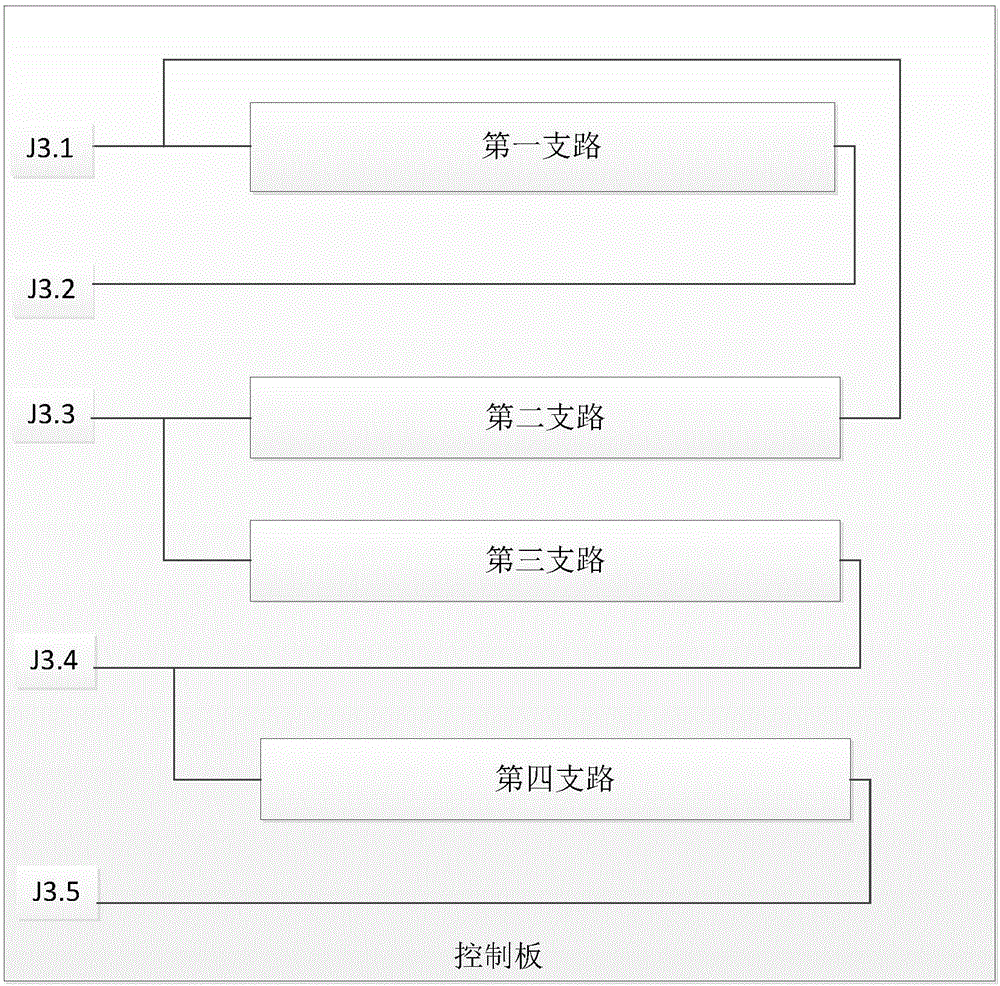
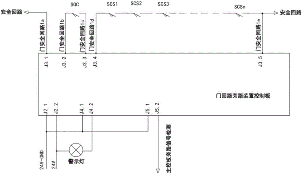
[0022] Appropriate reference figure 1 with figure 2 In the embodiment of the elevator door lock bypass device control board provided by the present invention, the elevator door lock bypass device control board is externally provided with a first interface J3.1, a second interface J3.2, and a third interface J3.3, For the fourth interface J3.4 and the fifth interface J3.5, the first branch, the second branch, the third branch and the fourth branch are set on the control board.
[0023] Among them, the first interface J3.1 is used to connect to the first node in the door safety circuit of the elevator, and the second interface J3.2 is used to connect to the second node in the door safety circuit. In the door safety circuit, there is no electrical switch between the first node and the second node. On the control board, a first branch is set between the first interface J3.1 and the second interface J3.2. This first branch is connected to the car door lock bypass switch BCD of the elevator. When the car door lock bypass switch BCD is turned on, the first branch is turned on. When the car door lock bypass switch BCD is closed, the first branch is turned on. The road is disconnected.
[0024] The third interface J3.3 is used to connect the third node in the door safety circuit. In the door safety circuit, the car door lock electrical switch is between the second node (or the first node) and the third node. On the control board, the first interface J3.1 and the third interface J3.3 are set up between the Two branch roads. This second branch is respectively connected to the elevator car door lock bypass switch BCD, the elevator's abnormal operation switch and the elevator landing door lock bypass switch BLD, and is next to the car door lock bypass switch BCD closed and the landing door lock When the circuit switch BLD is turned on and the abnormal operation switch of the elevator is turned off, the second branch is turned on, and when any one of the above three conditions is not met, the second branch is turned off.
[0025] The fourth interface J3.4 is used to connect the fourth node in the door safety circuit. In the door safety circuit, there is no electrical switch between the third node and the fourth node. On the control board, a third branch is set between the third interface J3.3 and the fourth interface J3.4. This third branch is connected to the elevator's floor door lock bypass switch BLD. When the floor door lock bypass switch BLD is opened, the third branch is turned on. When the floor door lock bypass switch BLD is closed, the third branch is turned on. The road is disconnected.
[0026] The fifth interface J3.5 is used to connect the fifth node in the door safety circuit. In the door safety circuit, between the fourth node and the fifth node are the electrical switches of the door locks in series with each other. On the control board, a fourth interface J3.4 and the fifth interface J3.5 are provided Branch road. This fourth branch is connected to the elevator car door lock bypass switch BCD, the elevator's abnormal operation switch and the elevator floor door lock bypass switch BLD, respectively, and the floor door lock bypass switch BLD is closed and next to the car door lock. When the road switch BCD is turned on and the abnormal operation switch of the elevator is turned off, the fourth branch is turned on, and the fourth branch is turned off when any one of the above three conditions is not met.
[0027] Using the elevator door lock bypass device control board provided by this embodiment, during normal operation, when the floor door lock bypass switch BLD and the car door lock bypass switch BCD are not operating (that is, open), the first branch The third branch is turned on, the second branch and the fourth branch are turned off, the control board has no effect on the door safety circuit, and the door safety circuit works normally.
[0028] In the process of abnormal operation, when the car door lock bypass switch BCD and the abnormal operation switch act (that is, closed), the first branch is disconnected, the second branch is turned on, the third branch is turned on, and the fourth branch is turned on. When the branch circuit is disconnected, the electrical switch of the car door lock is short-circuited, and the electrical switches of each floor door lock are normally connected in series in the door safety circuit. The elevator can perform abnormal operation when the car door is opened and the floor door is closed; or When the door lock bypass switch BLD and the abnormal operation switch act, the first branch is turned on, the second branch is disconnected, the third branch is disconnected, and the fourth branch is turned on. At this time, the electrical switches of each floor door lock If it is short-circuited, the elevator can perform abnormal operation when the car door is closed and the landing door is open.
[0029] In addition to the above two states, in one state, after the landing door lock bypass switch BLD or the car door lock bypass switch BCD is activated, as long as there is no abnormal operation switch action, the control panel is in the off state, and the elevator Can not operate. Therefore, even if the maintenance personnel forget to turn on the floor door lock bypass switch BLD or the car door lock bypass switch BCD, when the user operates the elevator by normal operation of the elevator, the elevator will not run, avoiding the shortcomings in the prior art. Safety accidents caused by untimely removal of the short wiring of the door safety circuit.
[0030] In the other state, after the floor door lock bypass switch BLD and the car door lock bypass switch BCD act simultaneously, even if the switch operates abnormally, the control panel will be in a disconnected state and the elevator cannot run. Avoid the potential safety hazards caused by the car door lock electrical switch and the landing door lock electrical switch being short-circuited at the same time, which may cause the elevator to perform maintenance operation while the car door and landing door are open at the same time.
[0031] Appropriate reference figure 2 with image 3 In another embodiment of the elevator door lock bypass device control board provided by the present invention, the elevator door lock bypass device control board is externally provided with a first interface J3.1, a second interface J3.2, and a third interface J3 .3. The fourth interface J3.4, the fifth interface J3.5, the fifteenth interface J4.1, the sixteenth interface J4.2, the seventeenth interface J5.1 and the eighteenth interface J5.2. The first branch, the second branch, the third branch, the fourth branch, the fifth branch and the sixth branch are arranged on the control board.
[0032] Among them, the first interface to the fifth interface, and the first branch to the fourth branch refer to the previous embodiment, and will not be repeated here.
[0033] The fifteenth interface J4.1 is used for grounding, the sixteenth interface J4.2 is used to connect the first end of the warning light of the elevator, the second end of the warning light is connected to the power supply, and the fifth branch is set at the fifteenth interface J4 Between .1 and the sixteenth interface J4.2. The fifth branch is connected to the elevator brake relay KMB (contact switch of the brake relay), car door lock bypass switch BCD and floor door lock bypass switch BLD respectively. During the elevator maintenance operation, the brake relay KMB and the car door lock bypass switch BCD act, or the brake relay and landing door lock bypass switch BLD act, at this time the fifth branch is turned on and the warning light is turned on, preferably Ground, the warning light adopts the hardware realization of sound and light alarm at the same time, so that when the elevator is in maintenance operation, the warning light is used as a warning to improve the safety of the maintenance operation.
[0034] The seventeenth interface J5.1 is grounded, the eighteenth interface J5.2 is connected to the bypass signal detection port of the elevator main control board, and the sixth branch is set at the seventeenth interface J5.1 and the eighteenth interface J5.2 between. The sixth branch is connected to the car door lock bypass switch BCD and the landing door lock bypass switch BLD respectively. When the car door lock bypass switch BCD or the landing door lock bypass switch BLD is activated, the sixth branch is turned on. The main control board can obtain the signal of the bypass signal detection port, and then when the elevator is bypassing, the main control board detects the door position switch.
[0035] Preferably, the abnormal operation switch of the elevator is an emergency electric operation switch SRR, a car top inspection operation switch SRT or a pit inspection operation switch SRP, and the second branch includes a first parallel branch group connected in series with the second branch, The first parallel branch group includes three parallel-connected first parallel first branches, first parallel second branches, and first parallel third branches. The fourth branch includes a first parallel connected in series to the fourth branch. Two parallel branch groups, the second parallel branch group includes three mutually parallel second parallel first branches, second parallel second branches and second parallel third branches.
[0036] Among them, the first parallel first branch and the second parallel first branch are both turned on when the emergency electric operation switch SRR is turned on, the car top inspection operation switch SRT is turned off, and the pit inspection operation switch SRP is turned off. The branch and the second parallel second branch are both turned on when the car top inspection operation switch SRT is turned on, the emergency electric operation switch SRR is turned off, and the pit inspection operation switch SRP is turned off. The first parallel third branch and the second parallel third branch are turned on. All three branches are turned on when the pit inspection operation switch SRP is turned on, the car top inspection operation switch SRT is turned off, and the emergency electric operation switch SRR is turned off.
[0037] Using this preferred embodiment, for elevators equipped with emergency electric operation switch SRR, car top inspection operation switch SRT, and pit inspection operation switch SRP, when the car door lock bypass switch BCD or the landing door lock bypass switch BLD is activated, And when any of the above abnormal operation switches act, the elevator can run.
[0038] Further preferably, the elevator door lock bypass device control board is realized by a relay, each switch is connected through the coil of the relay, and each branch is realized by the switch contact of the relay, which has higher reliability.
[0039] Specifically, the elevator door lock bypass device control board is also externally provided with a sixth interface J2.1, a seventh interface J2.2, an eighth interface J1.1, a ninth interface J1.2, a tenth interface J1.3, The eleventh interface J1.4, the twelfth interface J1.5, the thirteenth interface J1.6 and the fourteenth interface J1.7.
[0040] The sixth interface J2.1 is used for grounding; the seventh interface J2.2 is used to connect to the power supply; the eighth interface J1.1 is used to connect the emergency electric operation switch SRR, the car top inspection operation switch SRT, the pit inspection operation switch SRP, The first terminal of all the switches in the brake relay KMB, car door lock bypass switch BCD and landing door lock bypass switch BLD; the ninth interface J1.2 is used to connect the second terminal of the emergency electric operation switch SRR; the tenth interface J1.3 is used to connect the second end of the car top inspection operation switch SRT; the eleventh interface J1.4 is used to connect the second end of the pit inspection operation switch SRP; the twelfth interface J1.5 is used to connect the brake The second end of the relay; the thirteenth interface J1.6 is used to connect the second end of the car door lock bypass switch BCD; the fourteenth interface J1.7 is used to connect the second end of the floor door lock bypass switch BLD.
[0041] Among them, the eighth interface J1.1 is connected to the sixth interface J2.1; the coil K1 of the first relay is connected between the seventh interface J2.2 and the ninth interface J1.2; the coil K2 of the second relay is connected to Between the seventh interface J2.2 and the tenth interface J1.3; the coil K3 of the third relay is connected between the seventh interface J2.2 and the eleventh interface J1.4; the coil K4 of the fourth relay is connected to the Between the twelfth interface J1.5 and the seventh interface J2.2; the coil K5 of the fifth relay is connected between the seventh interface J2.2 and the thirteenth interface J1.6; the coil K6 of the sixth relay is connected to the Between the seven interface J2.2 and the fourteenth interface J1.7.
[0042] Wherein, the first branch includes the first normally closed switch K5-1 of the fifth relay.
[0043] The second branch includes a first parallel branch group connected in series, a second normally open switch K5-2 of the fifth relay, and a first normally closed switch K6-1 of the sixth relay, wherein the first parallel connection of the first branch The first normally open switch K1-1 of the first relay, the first normally closed switch K2-1 of the second relay, and the first normally closed switch K3-1 of the third relay that are connected in series with each other, the first is connected in parallel with the second branch Including the second normally closed switch K1-2 of the first relay connected in series, the second normally open switch K2-2 of the second relay and the second normally closed switch K3-2 of the third relay, the first parallel connected to the third branch The third normally closed switch K1-3 of the first relay, the third normally closed switch K2-3 of the second relay, and the third normally open switch K3-3 of the third relay are connected in series.
[0044] The third branch includes the second normally closed switch K6-2 of the sixth relay.
[0045] The fourth branch includes a second parallel branch group connected in series, a third normally closed switch K5-3 of the fifth relay, and a third normally open switch K6-3 of the sixth relay, wherein the second parallel connects the first branch Including the fourth normally open switch K1-4 of the first relay in series, the fourth normally closed switch K2-4 of the second relay and the fourth normally closed switch K3-4 of the third relay, and the second is connected in parallel with the second branch It includes the fifth normally closed switch K1-5 of the first relay, the fifth normally open switch K2-5 of the second relay and the fifth normally closed switch K3-5 of the third relay connected in series with each other, and the second is connected in parallel with the third branch The sixth normally closed switch K1-6 of the first relay, the sixth normally closed switch K2-6 of the second relay and the sixth normally open switch K3-6 of the third relay are included in series.
[0046] The fifth branch includes the first normally open switch K4-1 of the fourth relay, the fourth normally open switch K5-4 of the fifth relay connected in series with the first normally open switch K4-1 of the fourth relay, and the fifth relay. The fourth normally open switch K5-4 of the relay is connected in parallel with the fourth normally open switch K6-4 of the sixth relay.
[0047] The sixth branch includes a fifth normally open switch K5-5 of the fifth relay and a fifth normally open switch K6-5 of the sixth relay connected in parallel with each other.
[0048] Using this embodiment, during normal operation, when the floor door lock bypass switch BLD and the car door lock bypass switch BCD are both inactive (that is, open), the coil K5 of the fifth relay and the coil K6 of the sixth relay are both at In the power-off state, at this time, the first normally closed switch K5-1 of the fifth relay is closed, and the first branch is turned on; because the second normally open switch K5-2 of the fifth relay is opened, the second branch is turned off; The second normally closed switch K6-2 of the sixth relay is closed, and the third branch is turned on; because the third normally open switch K6-3 of the sixth relay is opened, the fourth branch is closed; because the fourth branch of the fifth relay The normally open switch K5-4 and the fourth normally open switch K6-4 of the sixth relay are both open, and the fifth branch is closed; due to the fifth normally open switch K5-5 of the fifth relay and the fifth normally open switch of the sixth relay The switches K6-5 are all turned on and the sixth branch is turned off. At this time, the control panel has no effect on the door safety circuit, and the door safety circuit works normally.
[0049] During the car top inspection operation, when the car door lock bypass switch BCD and the car top inspection operation switch SRT act (here only take the action of the car top inspection operation switch SRT as an example for illustration, the emergency electric operation switch SRR and pit inspection The operation switch SRP is the same and will not be repeated here), the coil K2 of the second relay is energized, the coil K4 of the fourth relay is energized, the coil K5 of the fifth relay is energized, and the coils of the other relays are in a de-energized state. At this time, the first normally closed switch K5-1 of the fifth relay is opened, and the first branch is closed; the second normally open switch K5-2 of the fifth relay is closed, and the second normally closed switch K1-2 of the first relay is closed. Closed, the second normally open switch K2-2 of the second relay is closed, the second normally closed switch K3-2 of the third relay is closed, the first normally closed switch K6-1 of the sixth relay is closed, and the second branch is turned on ; The second normally closed switch K6-2 of the sixth relay is closed, and the third branch is turned on; because the third normally open switch K6-3 of the sixth relay is opened, the fourth branch is turned off; the first of the fourth relay The normally open switch K4-1 is closed, the fourth normally open switch K5-4 of the fifth relay is closed, and the fifth branch is turned on; the fifth normally open switch K5-5 of the fifth relay is closed, and the sixth branch is turned on.
[0050] At this time, the electrical switch of the car door lock is short-circuited, and the electrical switches of each floor door lock are normally connected in series in the door safety circuit. The elevator can perform car top inspection operation when the car door is open and the floor door is closed. During operation, a warning The light produces a warning function, and the main control board can detect the bypass status signal.
[0051] During the car top inspection operation, when the landing door lock bypass switch BLD and the car top inspection operation switch SRT act (this place only takes the car top inspection operation switch SRT action as an example for illustration, the emergency electric operation switch SRR and pit inspection The operation switch SRP is the same and will not be repeated here), the coil K2 of the second relay is energized, the coil K4 of the fourth relay is energized, the coil K6 of the sixth relay is energized, and the coils of the other relays are in a de-energized state. At this time, the first normally closed switch K5-1 of the fifth relay is closed, and the first branch is turned on; because the second normally open switch K5-2 of the fifth relay is opened, the second branch is turned off; The second normally closed switch K6-2 is opened and the third branch is closed; the third normally open switch K6-3 of the sixth relay is closed, the fifth normally closed switch K1-5 of the first relay is closed, and the second relay is closed. The five normally open switch K2-5 is closed, the fifth normally closed switch K3-5 of the third relay is closed, the third normally closed switch K5-3 of the fifth relay is closed, and the fourth branch is turned on; the first of the fourth relay The normally open switch K4-1 is closed, the fourth normally open switch K6-4 of the sixth relay is closed, and the fifth branch is turned on; the fifth normally open switch K6-5 of the sixth relay is closed, and the sixth branch is turned on.
[0052] At this time, each floor door lock electrical switch is short-circuited, and the car door lock electrical switch is normally connected in series in the door safety circuit. The elevator can perform car top inspection operation when the car door is closed and the floor door is open. During operation, a warning The light produces a warning function, and the main control board can detect the bypass status signal.
[0053] In addition to the above two states, in one state, after the landing door lock bypass switch BLD or the car door lock bypass switch BCD is activated, as long as there is no abnormal operation switch action, due to the second branch and the fourth branch The groups of parallel branches in are all in the off state, so that the second branch and the fourth branch are both in the off state, so that the control board is in the off state, and the elevator cannot run.
[0054] In the other state, after the landing door lock bypass switch BLD and the car door lock bypass switch BCD act at the same time, even if the switch operates abnormally, since the first branch to the fourth branch are in the off state, The control panel will also be in a disconnected state, and the elevator cannot run.
[0055] Preferably, the control board further includes a coil K1 of the first relay, a coil K2 of a second relay, a coil K3 of a third relay, a coil K4 of a fourth relay, a coil K5 of a fifth relay, and a coil of the sixth relay, respectively, in parallel The diodes D1 to D6 of K6 protect each safety relay.
[0056] The present invention also provides an embodiment of an elevator control system. The elevator control system in this embodiment includes a door safety circuit, a car door lock bypass switch BCD, a landing door lock bypass switch BLD, an abnormal operation switch, and an elevator main Control board; and the elevator door lock bypass device control board described in any of the above embodiments, wherein the control board and door safety circuit, car door lock bypass switch BCD, landing door lock bypass switch BLD, abnormal The running switch and the elevator main control board are respectively connected to cut off the door safety circuit only when the car door lock bypass switch BCD or the landing door lock bypass switch BLD is closed, and only when the car door lock bypass switch BCD and abnormal When the operation switches are closed at the same time, short-circuit the electrical switch of the car door lock, and only short-circuit the electrical switches of each floor door lock when the floor door lock bypass switch BLD and the abnormal operation switch are closed at the same time.
[0057] The door safety circuit includes the car door lock electrical switch SQC and each floor door lock electrical switch SCS1-SCSn in series with each other. The car door lock bypass switch BCD and floor door lock bypass switch BLD are both rotary switches, with transparent PVC cover plates on them. , To prevent misoperation. The abnormal operation switch includes the car top inspection switch SRT, the elevator emergency electric switch SRR and the pit inspection switch SRP. The elevator control system also includes elevator brake relay KMB and bypass operation warning light.
[0058] In this embodiment, the contact string of the bypass switch is connected to the safety circuit to ensure that the safety circuit can be directly cut off when the bypass switch is activated to prevent the elevator from running. When either the car door lock or the landing door lock bypass switch is activated, one of the two maintenance switches and the emergency electric switch must be activated to ensure that the door safety circuit is turned on. It is realized that the elevator can only operate under emergency electric or maintenance operation. . The landing door lock bypass switch and the car door lock bypass switch form an interlock, so the car door lock electric switch and the landing door lock electric switch can only be short-circuited. The elevator brake action is equivalent to the elevator running. When any bypass switch is activated and the elevator is running, the circuit connecting the warning light is turned on. The warning light is composed of a light and a buzzer. When the elevator is running by bypass, the light is triggered . When the elevator is bypassing, the bypass signal of the control board is output to the main control board, and the main control board will detect the door position switch when the elevator is bypassing to ensure that the car door is in a closed state.
[0059] It can be seen from the above description that the elevator control system and the elevator door lock bypass device control board provided by the present invention have the following beneficial effects compared to the prior art: even if the maintenance personnel forget to switch the floor door lock bypass switch BLD or the car door When the lock bypass switch BCD is turned on, the elevator will not run when the user operates the elevator in the normal way of operating the elevator, which avoids the safety accident caused by the untimely removal of the short wiring of the short circuit door safety circuit in the prior art.
[0060] The sequence of the above embodiments is only for ease of description, and does not represent the merits of the embodiments.
[0061] Finally, it should be noted that the above embodiments are only used to illustrate the technical solutions of the present invention, not to limit them; although the present invention has been described in detail with reference to the foregoing embodiments, those of ordinary skill in the art should understand that: The technical solutions recorded in the foregoing embodiments are modified, or some of the technical features thereof are equivalently replaced; these modifications or replacements do not cause the essence of the corresponding technical solutions to deviate from the spirit and scope of the technical solutions of the embodiments of the present invention.
PUM


Description & Claims & Application Information
We can also present the details of the Description, Claims and Application information to help users get a comprehensive understanding of the technical details of the patent, such as background art, summary of invention, brief description of drawings, description of embodiments, and other original content. On the other hand, users can also determine the specific scope of protection of the technology through the list of claims; as well as understand the changes in the life cycle of the technology with the presentation of the patent timeline. Login to view more.