Supercharge Your Innovation With Domain-Expert AI Agents!

Heat pump type water heating drying system

A technology of drying system and heat pump system, applied in drying, drying machine, heating device and other directions, can solve the problem that the efficiency needs to be further improved, and achieve the effects of increasing pressure, increasing efficiency and reducing temperature

Active Publication Date: 2017-05-24
HENAN BAIHENG ENERGY SAVING TECH
View PDF30 Cites 5 Cited by
  • Summary
  • Abstract
  • Description
  • Claims
  • Application Information

AI Technical Summary

Problems solved by technology

The efficiency of the current heat pump drying system still needs to be further improved

Method used


Image

  • Heat pump type water heating drying system
  • Heat pump type water heating drying system
  • Heat pump type water heating drying system

Examples


Embodiment Construction

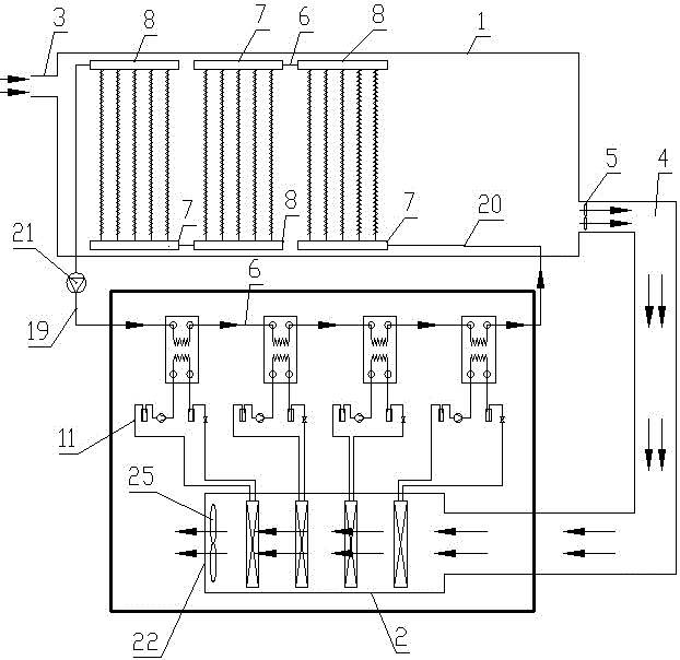
[0024] figure 1 The direction indicated by the middle arrow is the flow direction of the fluid (water or air).

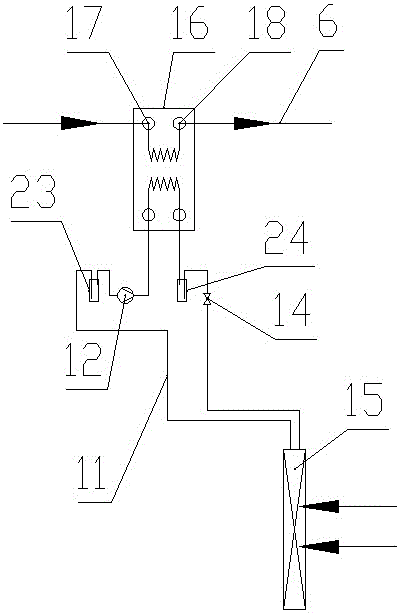
[0025] Such as figure 1 , figure 2 and image 3 As shown, the heat pump water heating drying system of the present invention includes a drying chamber 1, a heat pump system and an evaporation chamber 2; the left side of the drying chamber 1 is provided with an air inlet 3, and the right side of the drying chamber 1 is connected with a dehumidification air duct 4 , the first row of wet blowers 5 is arranged in the humidity exhaust air channel 4; more than two groups of fin units are arranged in the part adjacent to the air inlet 3 in the drying chamber 1, and each fin unit is connected in series through a hot water pipeline 6; The part of the drying chamber 1 adjacent to the dehumidification air duct 4 is a cavity for placing materials to be dried;

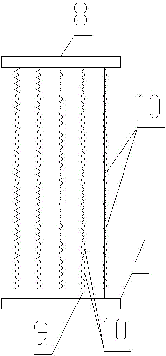
[0026] The structure of each fin unit is the same, including horizontal water inlet water collection pipe 7 and w...


PUM


Abstract

The invention discloses a heat pump type water heating drying system which comprises a drying chamber, heat pump systems and an evaporation chamber. The left side of the drying chamber is provided with an air inlet, the right side of the drying chamber is connected with a humidity elimination air flue, and the portion, close to the air inlet, inside the drying chamber is provided with two or more sets of fin units. Each heat pump system comprises a plate type heat exchanger, a compressor, a condenser, an expansion valve and an evaporator, wherein the compressor, the condenser, the expansion valve and the evaporator are circularly connected through a refrigerant pipeline, the condenser is located in the plate type heat exchanger, and the plate type heat exchanger is provided with a circulation water inlet and a circulation water outlet. The evaporators of the heat pump systems are arranged in the evaporation chamber side by side in a left-right mode at intervals. The left end of the evaporation chamber is provided with an air outlet. The right end of the evaporation chamber communicates with the humidity elimination air flue. The humidity in the drying chamber is lowered through fresh air. By the adoption of the heat pump type water heating drying system, materials can be rapidly dried through heated fresh air, and meanwhile the heat pump systems greatly saves energy, so that the heat pump type water heating drying system has the function of rapidly drying materials and the advantages of saving energy, reducing consumption and being free of pollution, and has quite good application and popularization prospects.

Description

technical field [0001] The invention relates to the technical field of material drying, in particular to a heat pump drying system. Background technique [0002] In industrial production, it is often necessary to dry materials. All drying equipment needs a heat source to provide the heat required for drying. Common sources of energy for heat sources include coal, natural gas and other energy sources that are difficult to regenerate. Among them, coal has the advantage of low cost, but coal is a non-renewable energy source. will pollute the atmosphere. Natural gas is a clean energy, but its high cost limits its application in industry. The heat pump system can concentrate the heat energy in the air to the condenser for use, and has the dual advantages of low cost and no environmental pollution. The efficiency of the current heat pump drying system still needs to be further improved. Contents of the invention [0003] The purpose of the present invention is to provide a h...

Claims


Application Information

Patent Timeline
Patent Type & Authority Applications(China)
IPC IPC(8): F26B9/06F26B21/00F26B23/10F26B25/00
CPCF26B9/06F26B21/003F26B23/005F26B23/10F26B25/00
Inventor 程烨李兴书冯云鹏杨德亮李长彬李童来海燕闫小广冯常伟
Owner HENAN BAIHENG ENERGY SAVING TECH
Features
  • R&D
  • Intellectual Property
  • Life Sciences
  • Materials
  • Tech Scout
  • Unparalleled Data Quality
  • Higher Quality Content
  • 60% Fewer Hallucinations
Learn More