induction motor
A technology of induction motor and direction of rotation, applied in asynchronous induction motors, electric components, electromechanical devices, etc., can solve the problems of increased second-order copper loss of high-order harmonics, increased components of high-order harmonics, and deterioration of motor characteristics.
- Summary
- Abstract
- Description
- Claims
- Application Information
AI Technical Summary
Problems solved by technology
Method used
Image


Examples
no. 1 approach
[0027] First, according to Figure 1 to Figure 4 , and the first embodiment will be described.
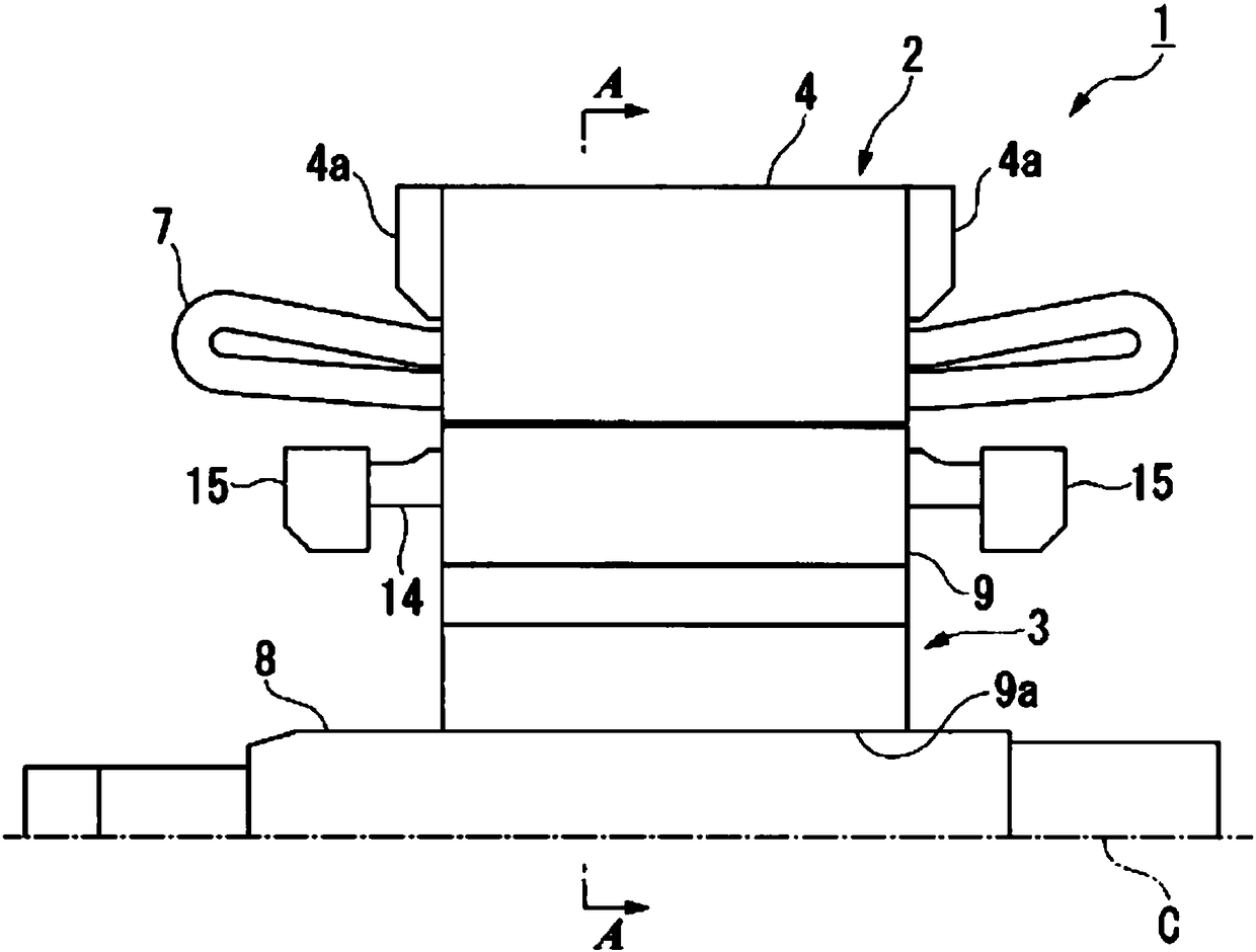
[0028] figure 1 It is a schematic configuration diagram of the induction motor 1 . figure 2 is along figure 1 Sectional view of line A-A.
[0029] Such as figure 1 , figure 2 As shown, the induction motor 1 includes a substantially cylindrical stator 2 and a rotor 3 , which are provided radially inward of the stator 2 and are provided rotatably relative to the stator 2 .
[0030] In addition, in the following figures, the scale of each member is appropriately changed for the sake of understanding and explanation. In the following description, the axial direction of the rotor 2 is simply referred to as the axial direction, the rotational direction of the rotor 2 is referred to as the circumferential direction, and the radial direction of the rotor 2 is simply referred to as the radial direction.
[0031] The stator 2 has a substantially cylindrical stator core 4 . The stat...
no. 2 approach
[0052] Next, according to image 3 , Figure 5 , Figure 6 , and the second embodiment will be described.
[0053] Figure 5 is a schematic configuration diagram of an induction motor 201 according to the second embodiment, and corresponds to the above-mentioned figure 2 Sectional view of line C-C. Figure 6 is along Figure 5 Sectional view of line D-D. In addition, in the following description, the same code|symbol is attached|subjected to the same structure as 1st Embodiment, and description is abbreviate|omitted (the same applies to the following embodiment).
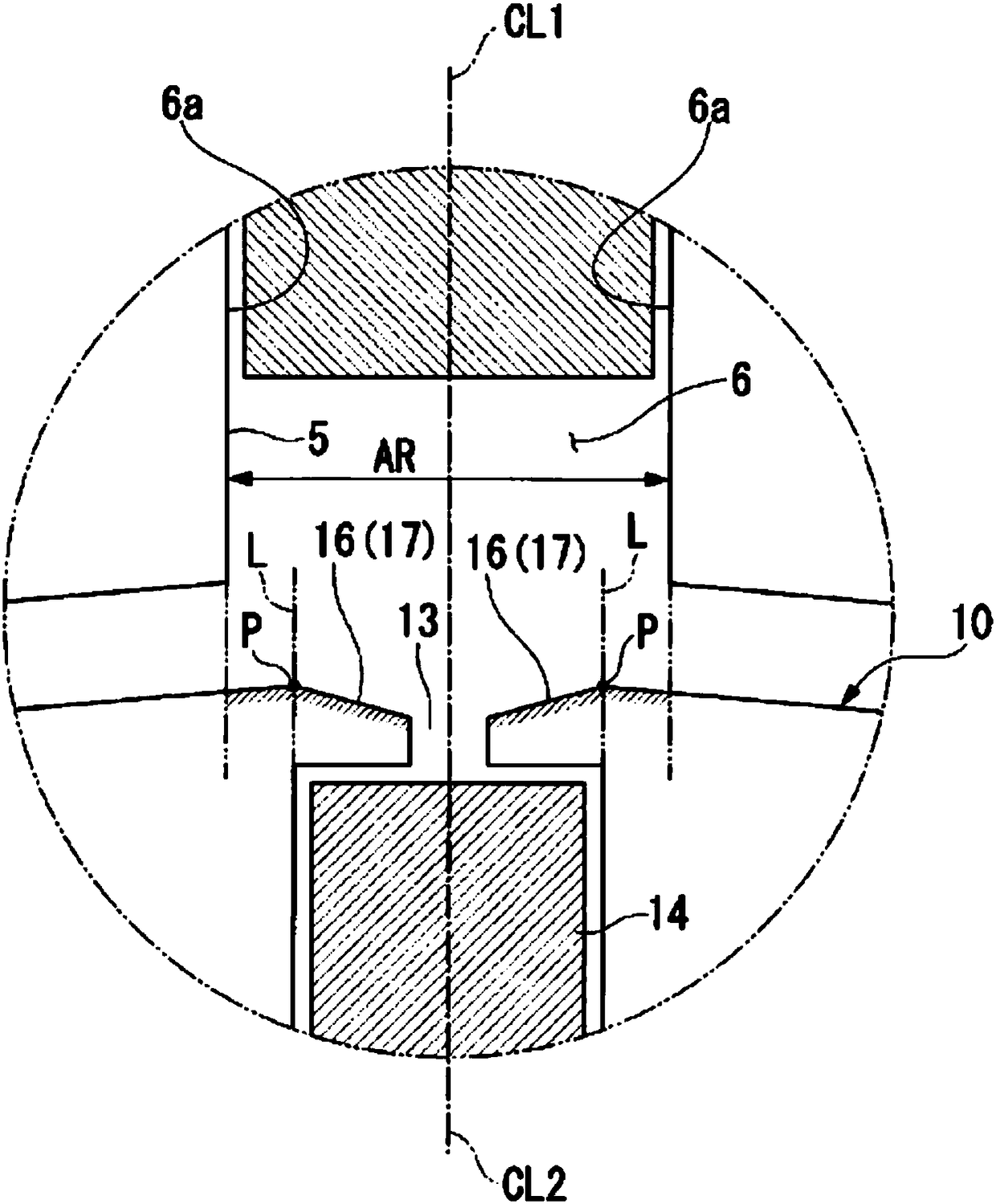
[0054] Such as Figure 5 , Figure 6 As shown, in this second embodiment, the depressed portion 16 (inclined surface 17) formed on the flange portion 12 of the rotor tooth 10 is not formed in the entire axial direction of the flange portion 12, but is formed avoiding the The positions of both ends of the rotor tooth 10 in the axial direction. This point is different from the first embodiment described abo...
no. 3 approach
[0062] Next, according to Figure 7 , Figure 8 , and the third embodiment will be described.
[0063] Figure 7 is a schematic configuration diagram of an induction motor 301 according to the third embodiment, and corresponds to the above-mentioned figure 2 Sectional view of line C-C. Figure 8 is along Figure 7 Sectional view of the H-H line.
[0064] Such as Figure 7 , Figure 8 As shown, in the third embodiment, the inclination of the depressed portion 16 (inclined surface 17 ) formed on the flange portion 12 of the rotor tooth 10 is set to gradually become steeper toward the center in the axial direction. This point is different from the first embodiment described above.
[0065] In addition, the cross-sectional shape of both ends of the rotor tooth 10 in the axial direction (along Figure 7 The shape of the cross-section of the F-F line) is the same as that of the above-mentioned second embodiment Figure 6 same. In addition, the cross-sectional shape (alon...
PUM
 Abstract
Description
Claims
Application Information
 - R&D
- Intellectual Property
- Life Sciences
- Materials
- Tech Scout
- Unparalleled Data Quality
- Higher Quality Content
- 60% Fewer Hallucinations
Browse by: Latest US Patents, China's latest patents, Technical Efficacy Thesaurus, Application Domain, Technology Topic, Popular Technical Reports.
© 2025 PatSnap. All rights reserved.Legal|Privacy policy|Modern Slavery Act Transparency Statement|Sitemap|About US| Contact US: help@patsnap.com