Supercharge Your Innovation With Domain-Expert AI Agents!

Calorimeter

A technology for a calorimeter and a heating device, applied in the field of calorimeters, can solve the problems of large overall volume and complex structure of the calorimeter, and achieve the effect of reducing the volume and simplifying the overall structure.

Pending Publication Date: 2017-05-31
长沙开元仪器有限公司
View PDF8 Cites 4 Cited by
  • Summary
  • Abstract
  • Description
  • Claims
  • Application Information

AI Technical Summary

Problems solved by technology

[0006] The purpose of the present invention is to provide a calorimeter to solve the problems of complex structure and large overall volume of the existing calorimeter, and reduce external auxiliary parts

Method used


Image

  • Calorimeter
  • Calorimeter

Examples


Embodiment 1

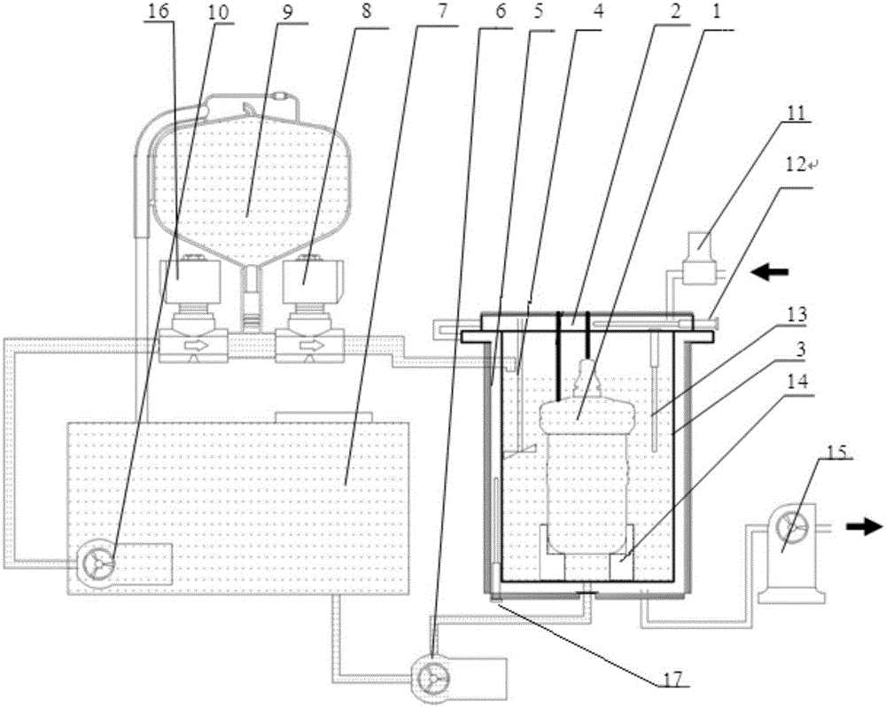
[0024] Such as figure 1 As shown, a calorimeter provided in this embodiment includes an oxygen bomb 1, an inner cylinder 3, an outer cylinder 5, a temperature control cover 2 and a control unit.

[0025] The oxygen bomb 1 is set in the inner cylinder 3 through the oxygen bomb bracket 14, the inner cylinder 3 is filled with liquid that has not passed through the oxygen bomb 1, and the inner cylinder 3 is provided with a meter for measuring the liquid. The temperature of the first temperature sensor 13 . The first temperature sensor 13 is connected with the control unit.

[0026] The outer cylinder 5 is sheathed on the outside of the inner cylinder 3 . An air interlayer is provided between the outer cylinder 5 and the inner cylinder 3 . The air interlayer is provided with a third temperature sensor 17 for measuring the temperature of the gas in the air interlayer, and the third temperature sensor 17 is connected with the control unit.

[0027] The temperature control cover 2...

Embodiment 2

[0035] This embodiment is basically the same as Embodiment 1. For the sake of brevity, in the description process of this embodiment, the same technical features as Embodiment 1 will not be described, and only the differences between this embodiment and Embodiment 1 will be described:

[0036] Wherein, the water circulation system of the inner cylinder is also included, and the water circulation system of the inner cylinder is used for replacing the liquid in the inner cylinder.

[0037] Wherein, the inner cylinder water circulation system includes a constant temperature water tank and a measuring cup, the water inlet of the constant temperature water tank is connected to the water outlet of the inner cylinder, and the water outlet of the constant temperature water tank is connected to the water inlet of the inner cylinder through the measuring cup A water inlet valve is provided at the connection between the water outlet of the constant temperature water tank and the measuring...


PUM


Abstract

The invention provides a calorimeter which comprises an oxygen bomb, an internal cylinder, an external cylinder, a temperature control lid and a control unit, wherein the oxygen bomb is arranged in the internal cylinder; the internal cylinder contains liquid higher than the oxygen bomb, and is provided with a first temperature sensor used for measuring liquid temperature; the external cylinder is sleeved outside the internal cylinder; an air interlayer is arranged between the external cylinder and the internal cylinder; the temperature control lid is connected with the external cylinder, and is provided with an air cavity communicated with the air interlayer; the temperature control lid and the external sleeve are provided with heating devices; the first temperature sensor and the heating devices are respectively connected with the control unit; and according to the liquid temperature in the internal cylinder, the heating devices are controlled to heat the gas in the air cavity and the air interlayer. According to the calorimeter, by means of arranging the air interlayer between the external cylinder and the internal cylinder, arranging the air cavity in the temperature control lid and heating the gas in the air cavity and the air interlayer through the heating devices, the temperature of the external cylinder is controlled, a complex external cylinder water route structure in a current adiabatic calorimeter is removed, the overall structure of the calorimeter is simplified, an thus the volume of the calorimeter is reduced; and the real-time control can be realized.

Description

technical field [0001] The invention relates to the technical field of calorific value measurement of exothermic substances, in particular to a calorimeter. Background technique [0002] Calorimeters are also called calorimeters, calorimeters or calorimeters. According to GB / T384 Determination of Calorific Value of Petroleum Products, the calorimeter is composed of a calorimetric vessel and the water, oxygen bomb, stirrer and thermometer in it. In order to ensure accurate determination of the calorific value of substances, the temperature of the outer and inner cylinders of the calorimeter and the oxygen bomb must be kept consistent. However, in most cases, it is unrealistic to ensure the stability of the ambient temperature for a long time. Descending will cause the outer barrel to absorb or release heat. Due to the different nature of endothermic and exothermic, and the degree of intensity is uncertain each time, the process is long. In this process, even if the temperat...

Claims


Application Information

Patent Timeline
IPC IPC(8): G01N25/20
CPCG01N25/20
Inventor 罗建文梁海东
Owner 长沙开元仪器有限公司
Features
  • R&D
  • Intellectual Property
  • Life Sciences
  • Materials
  • Tech Scout
  • Unparalleled Data Quality
  • Higher Quality Content
  • 60% Fewer Hallucinations
Learn More