Check patentability & draft patents in minutes with Patsnap Eureka AI!

LED light device

A technology for LED lamp devices and lamp holders, which is applied in the direction of lighting devices, gas-proof/waterproof devices, components of lighting devices, etc., can solve the problems of unstable connection, easy electric shock, poor contact, etc. The effect of avoiding electric shock hazard and improving stability

Inactive Publication Date: 2017-11-24
泰州明昕微电子有限公司
View PDF6 Cites 0 Cited by
  • Summary
  • Abstract
  • Description
  • Claims
  • Application Information

AI Technical Summary

Problems solved by technology

[0002] LED lamps have gradually replaced the existing incandescent lamps and fluorescent lamps to become a new generation of lighting equipment for daily life. When using LED lamps, the lamp body needs to be connected with the lamp holder. However, the connection between the lamp body and the lamp holder in the prior art is generally By plugging or clamping, the connection method is relatively unstable, and it is very easy to cause poor contact to cause blind lights. At the same time, the traditional power connection method of LED lights makes the power connection part often exposed to the outside world. It is very easy to cause electric shock accidents under human careless touch, and there is a great potential safety hazard

Method used


Image

  • LED light device
  • LED light device
  • LED light device

Examples


Embodiment Construction

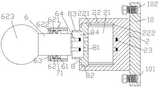
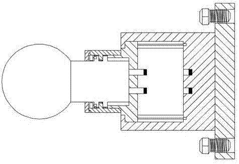
[0018] Such as Figure 1-Figure 4 As shown, an LED lamp device of the present invention includes a lamp head 6, a lamp holder 2 corresponding to the lamp head 6, and a fixing part 10 fixed to the lamp holder 2. The lamp The seat part 2 is provided with a cavity 21, and the upper and lower sides of the cavity 21 are correspondingly provided with a sliding cavity 22, and the sliding cavity 22 is provided with a stud 221, and the right end of the stud 221 is connected to the first motor 222 , the cavity 21 is provided with a sliding block 8, and the upper and lower sides of the sliding block 8 are correspondingly provided with bumps 82 penetrating into the sliding cavity 22, and the bumps 82 and the studs 221 are screw-shaped The left side of the sliding block 8 is provided with an external screw-shaped thread connection part 83, and the external thread-shaped thread connection part 83 is provided with a placement groove 84, and the slide on the right side of the placement groove...


PUM


Abstract

The invention discloses an LED lamp device. The device comprises a lamp holder part, a lamp base part corresponding to the lamp holder part and a fixed part fixed to the lamp base part; an accommodating cavity is formed in the lamp base part; sliding cavities are correspondingly formed in the upper side and the lower side of the accommodating cavity; studs are arranged in the sliding cavities; the right side ends of the studs are connected with first motors; a sliding block is arranged in the accommodating cavity; the upper side and the lower side of the sliding block are correspondingly provided with bulge blocks penetrating into the sliding cavities; the bulge blocks are in matched connection with spiral lines of the studs; an external spiral line rotating connecting part is arranged on the left side of the sliding block; a placing groove is formed in the external spiral line rotating connecting part; penetrating holes are formed in the sliding block on the right side of the placing groove; inserting spring holes are formed in the inner wall, corresponding to the right sides of the penetrating holes, of the lamp base part; and the left side of the placing groove corresponds to the lamp holder part. The device is simple in structure, convenient to operate and high in safety, loosening is prevented, and the electric shock danger caused by the fact that a person touches the inserting spring holes is effectively avoided.

Description

technical field [0001] The invention relates to the technical field of LED lamps, in particular to an LED lamp device. Background technique [0002] LED lamps have gradually replaced the existing incandescent lamps and fluorescent lamps to become a new generation of lighting equipment for daily use. When using LED lamps, the lamp body needs to be connected with the lamp holder. However, the connection between the lamp body and the lamp holder in the prior art is generally Through plugging or clamping, the connection method is relatively unstable, and it is easy to cause poor contact and lead to blind lights. At the same time, the traditional power connection method of LED lights makes the power connection part often exposed to the outside world. It is very easy to get an electric shock accident under the careless touch of human beings, and there is a great potential safety hazard. Contents of the invention [0003] The technical problem to be solved by the present inventi...

Claims


Application Information

Patent Timeline
Patent Type & Authority Patents(China)
IPC IPC(8): F21K9/232F21K9/235F21K9/237F21V31/00F21V17/12F21Y115/10
CPCF21V17/12F21V31/00
Inventor 石小平周丛林张方舒
Owner 泰州明昕微电子有限公司
Features
  • R&D
  • Intellectual Property
  • Life Sciences
  • Materials
  • Tech Scout
  • Unparalleled Data Quality
  • Higher Quality Content
  • 60% Fewer Hallucinations
Learn More