Optical disc library switch control device, method, equipment and optical disc data center
A switching control, data center technology, applied in optical recording/reproducing/erasing methods, program control in sequence/logic controllers, electrical program control, etc., can solve energy consumption and scalability constraints, data center data Capacity, operating costs, limited power resources, etc.
- Summary
- Abstract
- Description
- Claims
- Application Information
AI Technical Summary
Problems solved by technology
Method used
Image

Examples
Embodiment 1
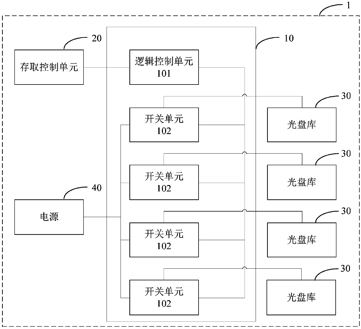
[0058] Such as figure 1 As shown, an embodiment of the present invention discloses an optical disc library switch control device 10, which is applied to an optical disc data center 1, including:
[0059] A logic control unit 101 and one or more switch units 102; wherein,
[0060] The logic control unit 101 is connected in communication with the access control unit 20 of the data center 1, and generates switch control logic signals for one or more optical disc libraries according to the data access signal of the access control unit 20;
[0061] The one or more switch units 102 are communicatively connected with the logic control unit 101, and the one or more switch units 102 are electrically connected between the one or more optical disc libraries 30 and the power supply 40, the one or more One or more switch units 102 are turned on or off according to the switch control logic signal, so that the one or more optical disc libraries 30 are turned on or off the power supply 40 . ...
Embodiment 2
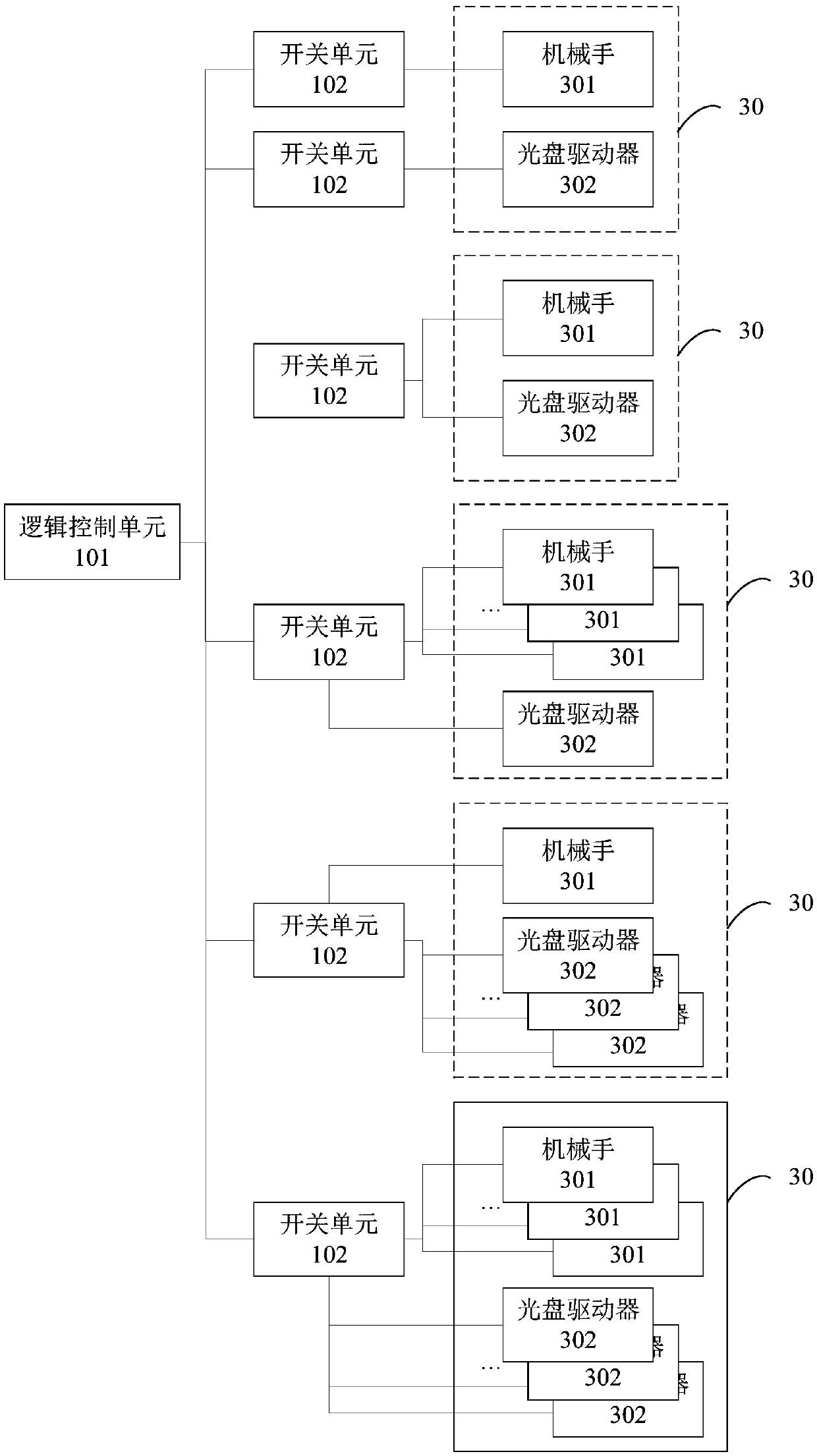
[0064] In one embodiment of the present invention, each optical disc library may also include one or more manipulators and one or more optical disc drives, so in the optical disc library switch control device, one or more switch units are further connected with the optical disc library The one or more robotic arms and / or the one or more optical disk drives are electrically connected so that the robotic arms and / or optical disk drives are powered on and off as required.
[0065] Specifically, such as figure 2 As shown, the switch unit 102 can be set corresponding to the manipulator 301 and / or the optical disc drive 302 in the optical disc library 30, and the corresponding mode can be 1:1 (one switch unit controls one manipulator or one switch unit controls one optical disc drive), or It can be 1:1:1 (one switch unit controls one manipulator and one optical disc drive at the same time), or 1:1:i (one switch unit controls one manipulator and i optical disc drives at the same tim...
Embodiment 3
[0068] In one embodiment of the present invention, in order to realize the automatic control of the switch unit by the logic control unit, preferably, the switch unit is an electronic switch, and the logic control unit can control the opening of each switch unit only through electronic signals / Close, so that the automatic control of the system can be realized.
[0069] More preferably, the electronic switch is further classified into an analog electronic switch and a digital electronic switch. Wherein, when an analog electronic switch is used, such as a relay, a triode, etc., the logic control unit includes a digital-to-analog converter, and the digital-to-analog converter performs digital-to-analog conversion on the digital data access signal to generate the switch Control logic signal; when using digital electronic switches, such as various types of triggers, etc., the logic control unit is a programmable logic device, which directly generates digital switch control logic s...
PUM
 Abstract
Description
Claims
Application Information
 - R&D
- Intellectual Property
- Life Sciences
- Materials
- Tech Scout
- Unparalleled Data Quality
- Higher Quality Content
- 60% Fewer Hallucinations
Browse by: Latest US Patents, China's latest patents, Technical Efficacy Thesaurus, Application Domain, Technology Topic, Popular Technical Reports.
© 2025 PatSnap. All rights reserved.Legal|Privacy policy|Modern Slavery Act Transparency Statement|Sitemap|About US| Contact US: help@patsnap.com