Hydrate promoter, device and method for continuously separating carbon dioxide from flue gas
A hydrate accelerator, carbon dioxide technology, applied in separation methods, chemical instruments and methods, dispersed particle separation, etc., can solve the problems of small processing capacity, high operating pressure, large compression energy consumption, etc., to promote generation, reduce surface Tension, the effect of suppressing excessive crystallization
- Summary
- Abstract
- Description
- Claims
- Application Information
AI Technical Summary
Problems solved by technology
Method used
Image

Examples
Example Embodiment
[0048] Method for continuous separation of carbon dioxide in flue gas Example 1
[0049] The main component (v / v) of the flue gas collected in this embodiment is N 2 : 75.1%, CO 2 : 20%, O 2 : 4.6%.
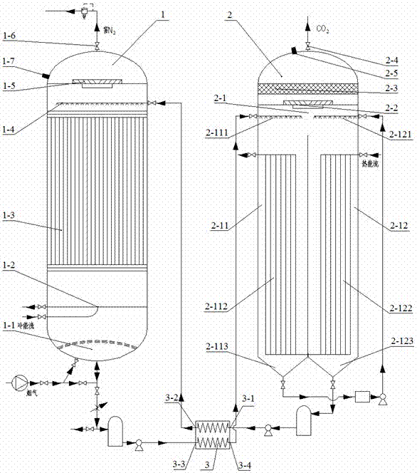
[0050] Continuously separate CO from flue gas in Example 1 2 The hydrate accelerator is made into an aqueous solution with a mass concentration of 4%, and the CO in the flue gas is continuously separated by the above 2 Device to control continuous CO 2 The flue gas flow pressure in the absorption tower is 0.33MPa and the temperature is 5℃, so that the flue gas and the atomized hydrate promoter solution flow relatively in the opposite direction, and the CO in the flue gas is realized on the wire netting bed. 2 Continuous capture; and then in the regeneration tower, at a pressure of 0.1013MPa, the heating device temperature of 85 ℃, to achieve CO 2 Decomposition of hydrate to remove CO 2 .
[0051] The specific operation is as follows: start continuous CO 2 The capture procedure of absorpt...
Example Embodiment
[0053] Method for continuous separation of carbon dioxide in flue gas Example 2
[0054] The main component (v / v) of the flue gas collected in this embodiment is N 2 : 69.7%, CO 2 : 28%, O 2 : 1.6%.
[0055] Example 2 Continuous separation of CO in flue gas 2 The hydrate accelerator is made into an aqueous solution with a mass concentration of 2.5%, and the CO in the flue gas is continuously separated by the above 2 Device to control continuous CO 2 The flue gas pressure in the absorption tower is 0.44MPa, and the temperature is 8℃, so that the flue gas and the atomized hydrate promoter solution flow relatively in the opposite direction, and the CO in the flue gas is realized on the wire mesh trap bed. 2 Continuous capture; and then in the regeneration tower, under the pressure of 0.088MPa, the heating device temperature of 60 ℃, to achieve CO 2 Decomposition of hydrate to remove CO 2 .
[0056] The specific operation method is the same as in Example 1.
[0057] After testing, continuo...
Example Embodiment
[0058] Method for continuous separation of carbon dioxide in flue gas Example 3
[0059] The main component (v / v) of the flue gas collected in this embodiment is N 2 : 69.7%, CO 2 : 28%, O 2 : 1.6%.
[0060] Continuously separate CO from flue gas in Example 3 2 The hydrate accelerator is made into an aqueous solution with a mass concentration of 7%, and the CO in the flue gas is continuously separated by the above 2 Device to control continuous CO 2 The flue gas flow pressure in the absorption tower is 0.55MPa and the temperature is 2°C, so that the flue gas and the atomized hydrate promoter solution flow relatively in the opposite direction, and the CO in the flue gas is realized on the wire netting bed. 2 Continuous capture; and then in the regeneration tower, the pressure is 0.088MPa, the heating device temperature is 70℃, to achieve CO 2 Decomposition of hydrate to remove CO 2 .
[0061] The specific operation method is the same as in Example 1.
[0062] After testing, continuous C...
PUM
 Abstract
Description
Claims
Application Information
 - R&D Engineer
- R&D Manager
- IP Professional
- Industry Leading Data Capabilities
- Powerful AI technology
- Patent DNA Extraction
Browse by: Latest US Patents, China's latest patents, Technical Efficacy Thesaurus, Application Domain, Technology Topic.
© 2024 PatSnap. All rights reserved.Legal|Privacy policy|Modern Slavery Act Transparency Statement|Sitemap