
Method and device for calculating standard depth/thickness ratio of coal mine goaf overhead transmission line

An overhead transmission line and calculation method technology is applied in the field of standard depth ratio of overhead transmission lines in goaf areas of coal mines, and can solve problems such as no standardized calculation method, no consideration of the properties of overlying layers, inconvenient engineering application, etc., and achieves wide applicability , the results are reliable, the effect of ensuring safety

Active Publication Date: 2017-07-11
国网山西省电力公司阳泉供电公司 +2
View PDF4 Cites 3 Cited by
  • Summary
  • Abstract
  • Description
  • Claims
  • Application Information

AI Technical Summary

Problems solved by technology

Although this method is widely used and simple, there are some problems. First, the depth-thickness ratio is generally determined based on experience, and there is no standardized calculation method; It is not convenient for engineering application; the third is that the current surface subsidence model essentially regards the overlying layer as a single medium, and determines the relevant limits based on experience, without considering the properties of the overlying layer

Method used


Image

  • Method and device for calculating standard depth/thickness ratio of coal mine goaf overhead transmission line
  • Method and device for calculating standard depth/thickness ratio of coal mine goaf overhead transmission line
  • Method and device for calculating standard depth/thickness ratio of coal mine goaf overhead transmission line

Examples


Embodiment 1

[0072] Example 1: The coal seam thickness of a coal mining face in a goaf is 2.65m, the mining thickness ratio λ=125.8, and the average inclination angle is 6°. The longwall caving coal mining method is adopted, and comprehensive mechanized coal mining is adopted. The mining depth is 330 meters To 360 meters, the surface undulation is not big. According to the strata histogram in the study area and the physical and mechanical experiment results of the rock and soil, the basic occurrence of the overlying layer and the physical and mechanical parameters of the rock and soil are determined as shown in Table 1. Now it is necessary to evaluate the surface deformation of the mining area by calculating the standard depth-thickness ratio.

[0073] Table 1: Layer parameters of the overlying layer

[0074]

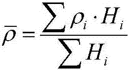
[0075] 1. Calculate the average density of each rock and soil layer overlying the goaf and density coefficient

[0076] Substitute the actual thickness and density paramete...


PUM


Abstract

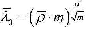
The invention relates to a method and a device for calculating the standard depth / thickness ratio of a coal mine goaf overhead transmission line. The method comprises the following steps: calculating the average density and the density coefficient of every rock and soil layer in goaf overlying strata; using the overlying rock and soil layer as a special medium, and calculating the inflection point depth / thickness ratio and the subsidence disturbance coefficient of the overlying rock and soil layer according to the average density, the density coefficient, the coal seam mining thickness and the inflection point depth / thickness ratio; and calculating the standard depth / thickness ratio according to the inflection point depth / thickness ratio and the subsidence disturbance coefficient of the overlying layer. The device includes an average density calculation module, a density coefficient calculation module, an inflection point depth / thickness ratio calculation module, a subsidence disturbance coefficient calculation module, a standard depth / thickness ratio calculation module and a maximum subsidence rate calculation module. The method considers the influences of the density of the overlying layer, the mining depth and the thickness on surface deformation, compares the obtained standard depth / thickness ratio with the number 1, analyzes the relationship between the relation between the standard depth / thickness ratio and the surface deformation, and solves the standard disunity problem caused by geological differences of different areas. The device can accurately calculate the standard depth / thickness ratio and the maximum subsidence rate.

Description

technical field [0001] The invention belongs to the field of disaster prevention design and protection of overhead power transmission lines, and in particular relates to a calculation method and device for the standard depth-thickness ratio of overhead power transmission lines in goaf areas of coal mines. Background technique [0002] High-voltage transmission lines are the main channel for long-distance power transmission, and they must be safe, reliable and foolproof during operation. After the underground coal mine is mined, it will form a mining-influenced area, which will cause mining deformation on the surface. When the transmission tower is located in the mining-affected area, because it is extremely sensitive to the ground movement and deformation caused by mining, the safety of high-voltage transmission lines will be greatly affected. The evaluation of the surface stability of coal mine goaf is especially important for the safe and reliable operation of transmissio...

Claims


Application Information

Patent Timeline
IPC IPC(8): G01N33/24
CPCG01N33/24
Inventor 穆昭玺张慧明贾志义任学武高枫
Owner 国网山西省电力公司阳泉供电公司
Features
  • Generate Ideas
  • Intellectual Property
  • Life Sciences
  • Materials
  • Tech Scout
  • Unparalleled Data Quality
  • Higher Quality Content
  • 60% Fewer Hallucinations
Learn More