

Graphene nanosheet pair array
A technology of graphene nanosheets and nanosheets, which is applied in the direction of material analysis, instrumentation, and transmittance measurement by optical means.
- Summary
- Abstract
- Description
- Claims
- Application Information
AI Technical Summary
Problems solved by technology
Method used
Image

Examples
Embodiment 1
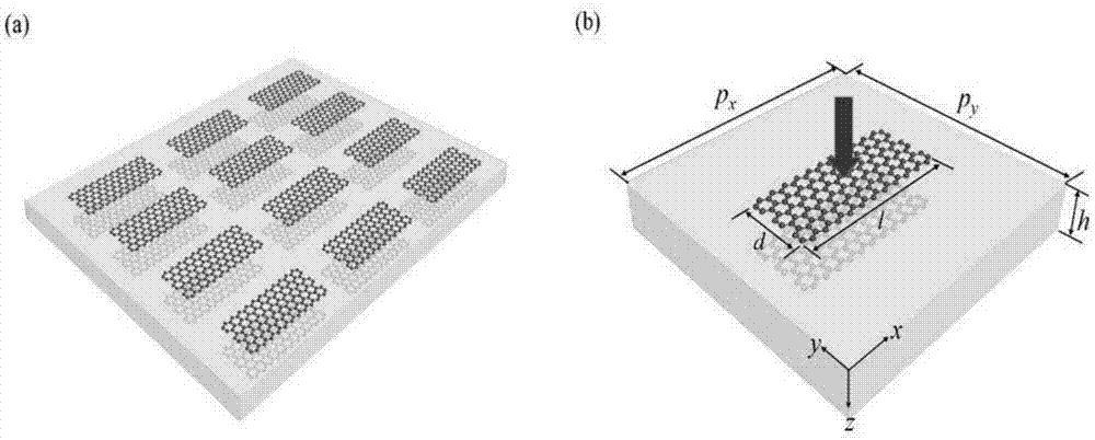
[0044] Used as a dynamically tunable plasmonic bandstop filter based on single-layer graphene and bilayer graphene.
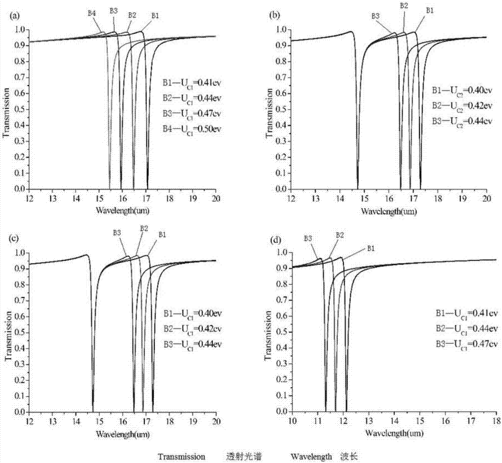
[0045] The transmission spectra at different chemical potentials with single-layer graphene were studied. figure 2(a) shows the simulated transmission spectra at the chemical potential of the lower graphene μc2 = 0.1 eV and the chemical potential μc1 of the upper graphene increasing from 0.41 eV to 0.50 eV. The resonance wavelength is obviously blue-shifted by 1.62um, and μc1 is increased by 0.9ev. figure 2 (b) shows that when we adjust μc2 from 0.40ev to 0.44ev and keep μc1=0.55ev, one resonance wavelength is blue-shifted, while the other resonance wavelength does not change. When μc2=0.55ev and μc1 increases from 0.40ev to 0.44ev, we can get the same as figure 2 (b) the same result as figure 2 (c) shown. It is shown that the two resonance wavelengths are simultaneously and independently tuned by μc1 and μc2. The resonant wavelength can be tuned drama...
Embodiment 2
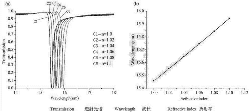
[0048] used as an optical sensor based on a model with an array of single-layer graphene nanosheet pairs. The sensing performance of the model with single-layer nanosheet pair arrays at μc1 = 0.1 eV and μc2 = 0.5 eV was investigated. implement a transmissive tilt, and the image 3 The transmission spectra of this model at different background refractive (n) rates from 1.0 to 1.1 are shown in (a). It shows that a small change in the background refractive index results in a clear shift in the peak position. The transmission (T) at the peak position remains almost constant at 0.0012, and the half-wave width hardly changes with the background refractive index. As the background refractive index (n) increases, the resonance wavelength has a nearly linear increase, as image 3 (b) shown. The optical sensor is characterized by the linewidth of the resonance (Δλ) and the shift (s) of the resonance wavelength per refractive index unit change. Δλ, s and FOM are given by the formula...
Embodiment 3
[0050] used as a two-circuit optical switch based on a structure with an array of single-layer graphitic nanosheet pairs.
[0051] A dual-circuit optical switch based on a single-layer structure is proposed. other parameters with figure 2 (a) Same, except for the chemical potentials of the upper and lower graphene μc1, μc2. By adjusting the values of μc1 and μc2, the transmission of the resonant wavelength can be controlled, as Figure 4 shown. This shows up in Figure 4 Two transmission tilts independently controlled by μc1 and μc2 in (a), μc1=0.4ev and μc2=0.5ev. When we only adjust the value of μc2 to 0.1ev and keep μc1=0.4ev, the first tilt disappears, as Figure 4 (b) shown. and Figure 4 (a) compared to, Figure 4 (c) shows that at μc2 = 0.5ev, μc1 = 0.1ev, the transmission at the second resonance wavelength is close to 1, but the transmission at the first resonance wavelength remains at the same value. will μ c1 and μ c2 Both were tuned to 0.1 eV, and the ...
PUM
| Property | Measurement | Unit |
|---|---|---|
| width | aaaaa | aaaaa |
| length | aaaaa | aaaaa |
| refractive index | aaaaa | aaaaa |
Abstract
Description
Claims
Application Information