Drawing die structure

A drawing die and die technology, applied in the field of drawing die die structure, can solve the problems that the press table cannot meet the requirements, the drawing die size is too long and wide, and the 2' width of the blank holder is large, etc. Thickness, reduced requirements, effect of size reduction

Active Publication Date: 2017-08-15
ANHUI JIANGHUAI AUTOMOBILE GRP CORP LTD
View PDF5 Cites 0 Cited by
  • Summary
  • Abstract
  • Description
  • Claims
  • Application Information

AI Technical Summary

Problems solved by technology

[0006] In the prior art, the drawing die of the assembly relationship between the blank holder 2' and the punch 3', in order to ensure the strength of the blank holder 2', the radial thickness of the blank holder 2'

Method used


Image

  • Drawing die structure
  • Drawing die structure
  • Drawing die structure

Examples


Example Embodiment

[0029] The embodiments described below by referring to the figures are exemplary only for explaining the present invention and should not be construed as limiting the present invention.

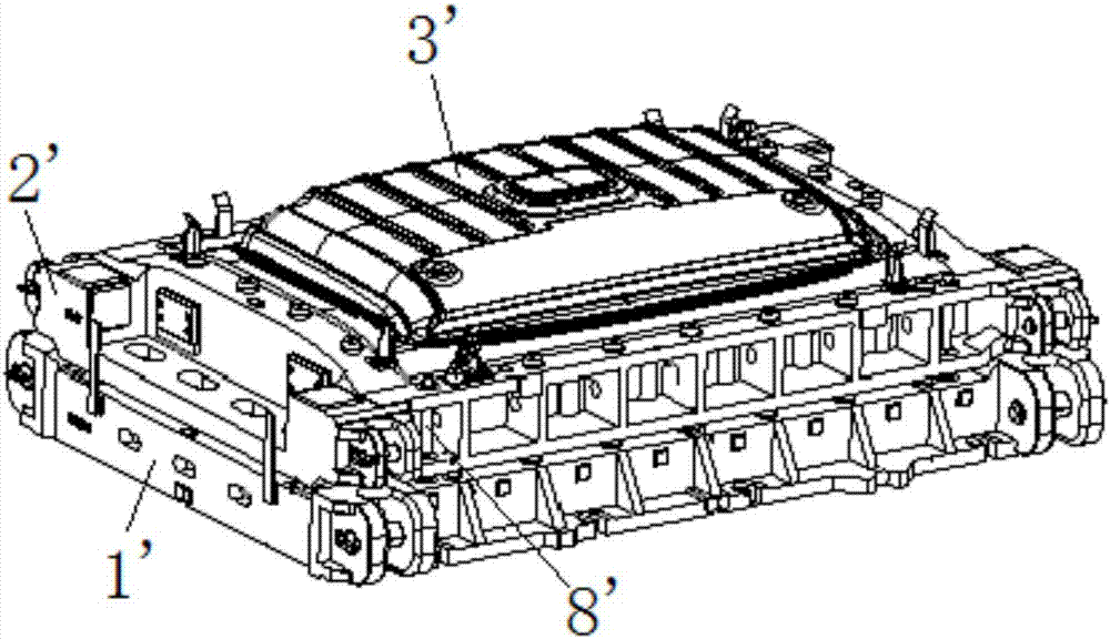
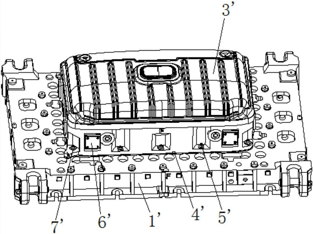
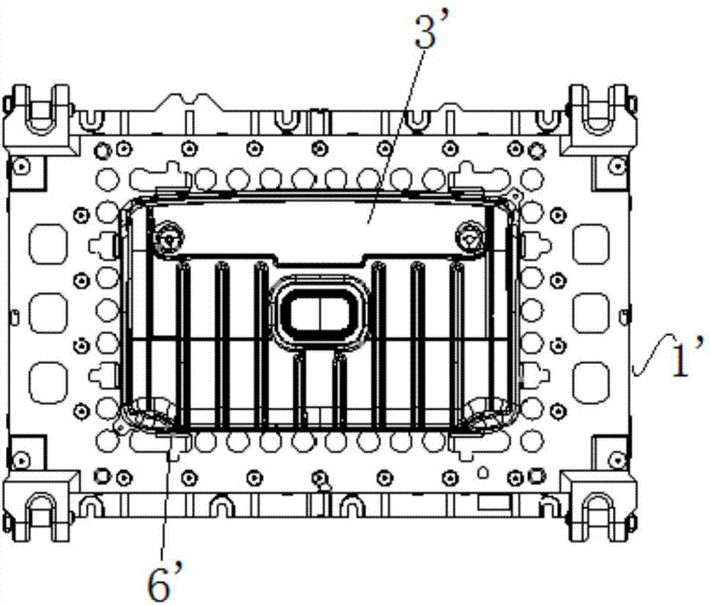
[0030] Figure 4 The schematic diagram of the installation of the punch and the punch seat proposed for the specific embodiment of the present invention; Figure 5 A schematic structural view of the punch seat proposed for a specific embodiment of the present invention; Image 6 The top view of the punch and the punch seat proposed for the specific embodiment of the present invention; Figure 7 It is a schematic structural diagram of a blank holder proposed in a specific embodiment of the present invention.

[0031] Please refer to Figure 4 to Figure 7 , the present invention proposes a drawing die structure, which includes a punch base 1, a blank holder 2, a punch 3 and a safety stroke bolt 8', and the punch base 1 is provided with a mounting platform 4, so The punch 3 is installed on t...


PUM


Abstract

The invention discloses a drawing die structure which comprises a male die seat, a binder ring and a male die. The male die seat is provided with an installation table, and the male die is installed on the side, away from the male die seat, of the installation table; the male die is installed on the male die seat through installation keys and bolts, and the four installation keys are located at the upper edges of the four side faces of the installation table correspondingly; the projection of the installation table on the male die seat is located in the projection of the male die on the male die seat; the side faces of the installation tables are provided with first guide sliding faces, the projections of the first guide sliding faces on the male die seat are located in the projection of the male die on the male die seat; and the binder ring is installed on the male die seat through safe stroke bolts, and the inner wall of the binder ring is provided with second guide sliding faces matched with the first guide sliding faces. The drawing die structure is small in size while meeting the same rigidity condition.

Description

technical field [0001] The invention relates to the technical field of drawing dies, in particular to a drawing die structure. Background technique [0002] In the design of large-scale stamping parts, especially outer cover parts, in order to ensure the formability of stamping parts and the structural strength of the mold, the size of the mold is generally relatively large. At present, the length of most machine tool tables is 4.5 meters and the width is 2.5 meters. Some large stamping parts have a mold size larger than this size, and part of the mold structure will be exposed outside the machine tool table, which not only affects the formability of stamping parts, but also has certain safety hazards . Although the tabletop can be increased by repurchasing or transforming the machine tool, this method is costly and economically poor. [0003] In prior art, please refer to Figure 1 to Figure 3 , figure 1 It is a structural schematic diagram of a drawing die disclosed in...

Claims


Application Information

Patent Timeline
IPC IPC(8): B21D37/12B21D22/22
CPCB21D22/22B21D37/12
Inventor 王肖英王星罡张国兵黄顶社黄永生孙晓
Owner ANHUI JIANGHUAI AUTOMOBILE GRP CORP LTD
Why Eureka
Try Eureka