Check patentability & draft patents in minutes with Patsnap Eureka AI!

Eccentric oscillating gear unit

A technology of gear device and eccentric swing, applied in the direction of gear transmission device, transmission device, transmission device parts, etc., can solve the problem of difficult to fully ensure the bearing support capacity for supporting the crankshaft, and achieve the effect of increasing the support capacity

Active Publication Date: 2020-12-01
SUMITOMO HEAVY IND LTD
View PDF10 Cites 0 Cited by
  • Summary
  • Abstract
  • Description
  • Claims
  • Application Information

AI Technical Summary

Problems solved by technology

[0006] In such an eccentric oscillating gear unit, there is a problem that it is difficult to sufficiently ensure the supporting capacity of the bearing supporting the crankshaft.

Method used


Image

  • Eccentric oscillating gear unit
  • Eccentric oscillating gear unit
  • Eccentric oscillating gear unit

Examples


Embodiment Construction

[0018] Hereinafter, an example of embodiment of the present invention will be described in detail based on the drawings.

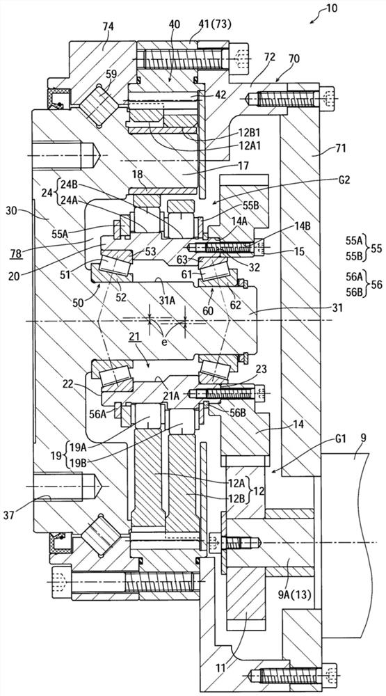
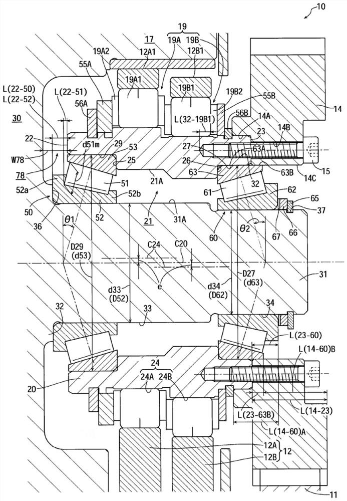
[0019] figure 1 It is a sectional view showing the structure of an eccentric oscillating gear device according to an example of an embodiment of the present invention, figure 2 yes figure 1 An enlarged view of the main part.

[0020] Roughly speaking, the gear unit 10 includes two external gears (oscillating gears) 12 ( 12A, 12B) and a crankshaft 20 for oscillating and rotating the external gears 12 . The gear unit 10 includes a carrier (flange member) 30 arranged to face the crankshaft 20 in the axial direction, and the external gear 12 and the internal gear 40 (not Swing gear) between the relative rotation.

[0021] The crankshaft 20 has a hollow portion 21 , and the wheel carrier 30 has a shaft member 31 inserted into the hollow portion 21 . In addition, inner bearings (the first inner bearing 50 and the second inner bearing 60 ) are disposed betw...


PUM


Abstract

The invention provides an eccentric rocking type spur gearing which can further increase the support capacity of a bearing of a supporting crankshaft. The eccentric rocking type spur gearing (10) comprises a rocking gear (12), a crankshaft (20) for enabling the rocking gear to rock and rotate and a flange part (30) oppositely arranged with the crankshaft in axial direction, wherein the crankshaft comprises a hollow portion (21), the flange part comprises a shaft part (31) which inserts in the hollow portion, an inner side gearing (50, 60) is arranged between the inner circumference (21A) of the crankshaft and the outer circumference (31A) of the shaft part, and the inner side gearing protrudes L (22-50) and L(23-60) along the axial direction from the axial end face (22, 23) of the crankshaft.

Description

[0001] This application claims priority based on Japanese Patent Application No. 2016-024346 filed on February 12, 2016. The entire contents of this Japanese application are incorporated herein by reference. technical field [0002] The present invention relates to an eccentric oscillating gear device. Background technique [0003] For example, Patent Document 1 discloses an eccentric oscillating type gear device. This gear unit includes a swing gear and a crankshaft that swings and rotates the swing gear. In addition, a flange member arranged to face the crankshaft in the axial direction is further provided, and the relative rotation between the swing gear and the non-swing gear side obtained by swinging of the swing gear is output from the flange member. [0004] The crankshaft has a hollow portion, and a shaft member protruding from the flange member is inserted into the hollow portion. The crankshaft is supported by bearings arranged between the inner periphery of the...

Claims


Application Information

Patent Timeline
Patent Type & Authority Patents(China)
IPC IPC(8): F16H1/32F16H57/023F16H57/08F16C3/06
CPCF16C3/06F16H1/32F16H57/023F16H57/08F16H2001/323F16H2001/327
Inventor 志津庆刚芳贺卓
Owner SUMITOMO HEAVY IND LTD
Features
  • R&D
  • Intellectual Property
  • Life Sciences
  • Materials
  • Tech Scout
  • Unparalleled Data Quality
  • Higher Quality Content
  • 60% Fewer Hallucinations
Learn More