Supercharge Your Innovation With Domain-Expert AI Agents!

Edge light guide plate and backlight module

A light guide plate, side entry technology, applied in the direction of light guide, optics, optical components, etc., can solve the problems of insufficient concentration of light, large diffusion range, poor localdimming effect, etc., to achieve the effect of improving the effect, reducing the power consumption of the device, and improving the contrast ratio.

Inactive Publication Date: 2017-08-29
WUHAN CHINA STAR OPTOELECTRONICS TECH CO LTD
View PDF6 Cites 4 Cited by
  • Summary
  • Abstract
  • Description
  • Claims
  • Application Information

AI Technical Summary

Problems solved by technology

[0004] At present, the light emitted by the light source located on the side of the light guide plate enters from the light incident surface of the light guide plate. Due to technical defects, the light is not concentrated enough and has a large diffusion range, thus forming a large bright area on the light guide plate, resulting in local dimming less effective

Method used


Image

  • Edge light guide plate and backlight module
  • Edge light guide plate and backlight module
  • Edge light guide plate and backlight module

Examples


Embodiment Construction

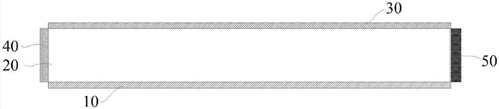
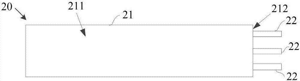
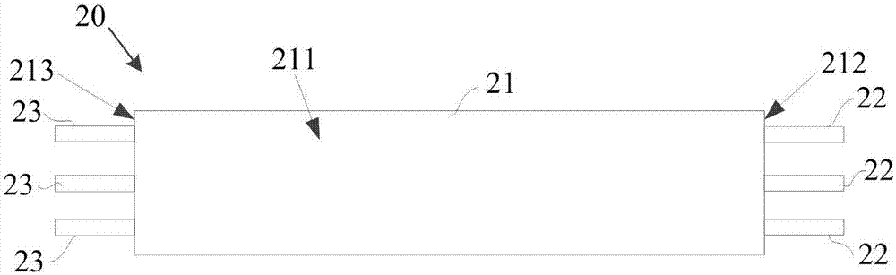
[0028] The description of the following embodiments refers to the attached drawings to illustrate specific embodiments that the present invention can be implemented. The directional terms mentioned in the present invention, such as "up", "down", "front", "rear", "left", "right", "inner", "outer", "side", etc., are for reference only The direction of the additional schema. Therefore, the directional terms used are used to describe and understand the present invention, rather than to limit the present invention.

[0029] In the drawings, modules with similar components are denoted by the same reference numerals.

[0030] In addition, the terms "first" and "second" are only used for descriptive purposes, and cannot be understood as indicating or implying relative importance or implicitly indicating the number of indicated technical features. Thus, the features defined with "first" and "second" may explicitly or implicitly include one or more of these features. In the description of...


PUM


Abstract

The invention provides an edge light guide plate and a backlight module. The edge light guide plate comprises a light guide portion having a first light incident surface and a light emitting surface. The first light incident surface intersects the light emitting surface. The first light incident surface is provided with a plurality of first light guide columns protruding from the first light incident surface so that light enters the light guide portion through the plurality of first light guide columns and is emitted from the light emitting surface. According to the scheme, the light enters the light guide plate through the light guide columns by arranging the light guide columns on the light incident surface of the light guide plate. The light is concentrated and low in diffusion range due to the constraint of the light guide plate. Thus, a small bright area is formed in the light guide plate so as to enhance a local backlight adjustment effect, thereby enhancing the contrast of a LCD screen and reducing device power consumption.

Description

Technical field [0001] The present invention relates to the field of liquid crystal display panel manufacturing, in particular to an edge-type light guide plate and a backlight module. Background technique [0002] The core of the display technology is to reproduce the human eye's perception of the real world. The current mainstream display technologies include LCD (Liquid Crystal Display) and OLED (Organic Light-Emitting Diode). Among them, LCD display technology has a long history of development, and has the advantages of mature technology, low cost, and high reliability. Its main principle is to provide illumination through full-surface or large-area full-bright backlight, and then through TFT (ThinFilm Transistor) (Transistor) controls and drives the liquid crystal, as a light valve to achieve sub-pixel level brightness modulation. [0003] Among them, the backlight module occupies an important position in LCD display technology. If the backlight module has a local dimming (l...

Claims


Application Information

Patent Timeline
Patent Type & Authority Applications(China)
IPC IPC(8): G02B6/00G02F1/13357
CPCG02B6/0013G02B6/0028G02F1/133615G02B6/0041G02B6/0068
Inventor 李晓玲梁超
Owner WUHAN CHINA STAR OPTOELECTRONICS TECH CO LTD
Features
  • R&D
  • Intellectual Property
  • Life Sciences
  • Materials
  • Tech Scout
  • Unparalleled Data Quality
  • Higher Quality Content
  • 60% Fewer Hallucinations
Learn More