Supercharge Your Innovation With Domain-Expert AI Agents!

Fiber interface module

An optical fiber interface component and optical fiber technology, applied in the field of optical fiber interface components, can solve the problems of low coupling power that cannot meet the requirements of communication, deviation of the consistency of laser output angle, complex manufacturing process, etc., to achieve high return loss and improve product performance , the effect of reducing production costs

Pending Publication Date: 2017-08-29
深圳市惠富康光通信有限公司
View PDF7 Cites 2 Cited by
  • Summary
  • Abstract
  • Description
  • Claims
  • Application Information

AI Technical Summary

Problems solved by technology

[0004] The purpose of the present invention is to provide an optical fiber interface assembly, which aims to solve the problem of complex manufacturing process and high technical requirements in the prior art, and there is deviation in the consistency of the laser output angle during the packaging process, which leads to low coupling power and cannot meet the requirements for communication use.

Method used


Image

  • Fiber interface module
  • Fiber interface module
  • Fiber interface module

Examples


Embodiment Construction

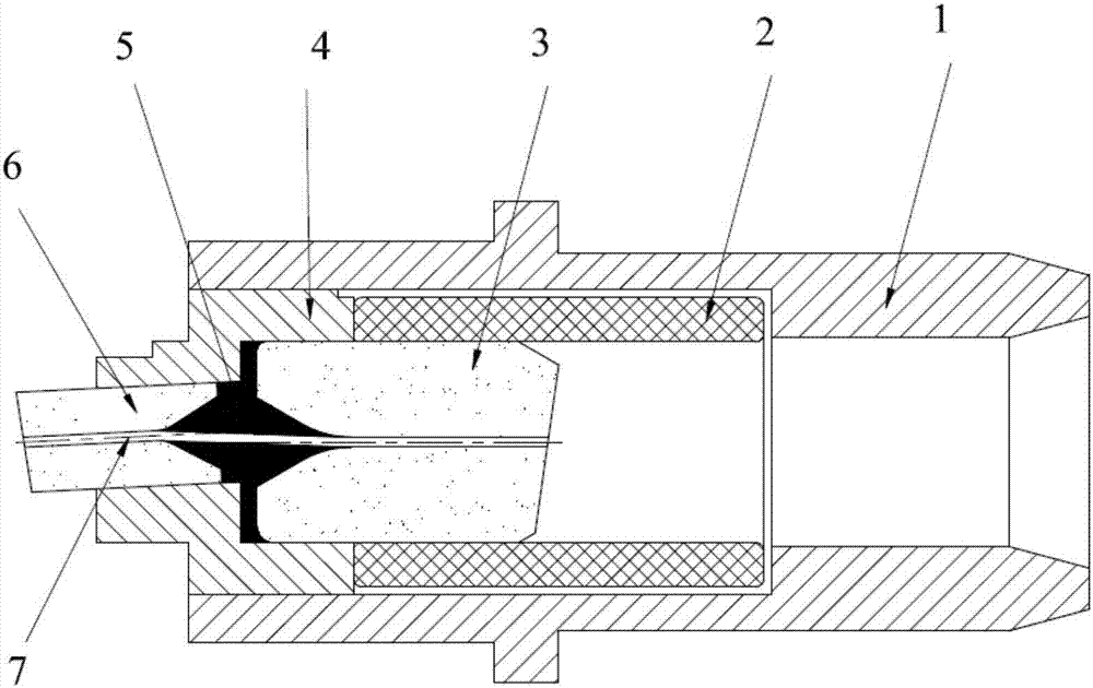
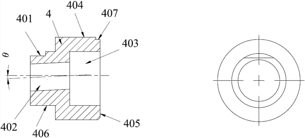
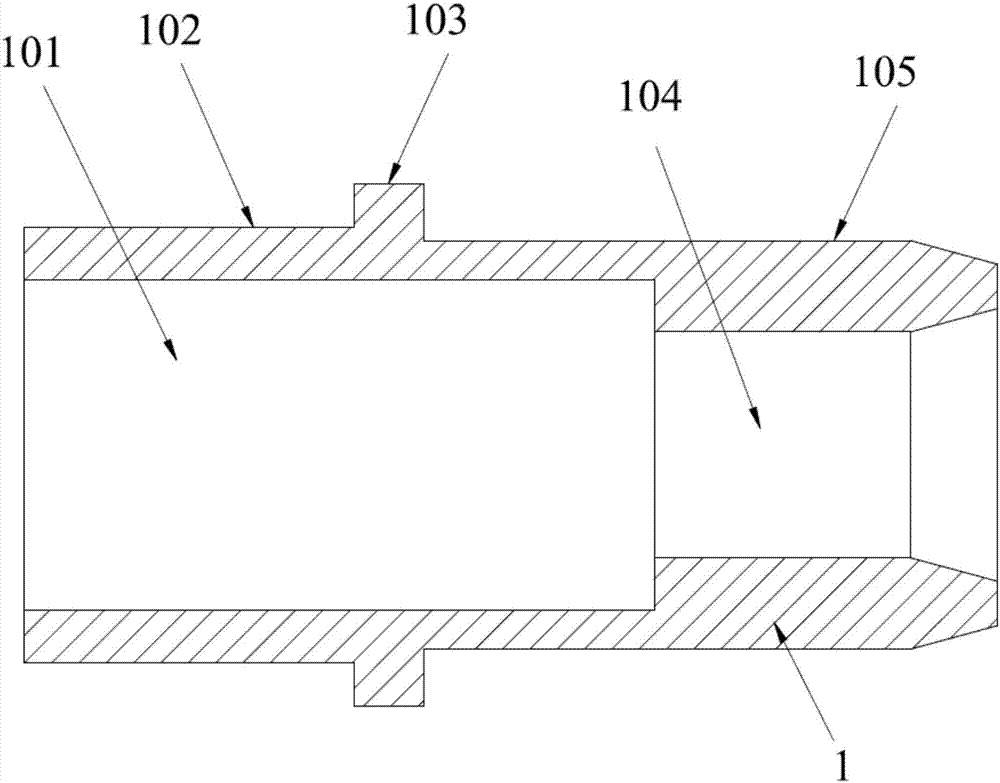
[0020] Such as figure 1 As shown, the optical fiber interface assembly includes a metal tail plug 1, a ceramic sleeve 2, a second ceramic ferrule 3, a metal base 4, a first ceramic ferrule 6 and an optical fiber 7, and the ceramic sleeve 2 is arranged on the In the middle of the metal tail plug 1, the metal base 4 includes a first cavity 402 and a second cavity 403, the first cavity 402 is arranged on the top of the second cavity 403 and communicated with each other, and the first cavity 402 is connected to the top of the second cavity 403. There is an included angle between the central axis of a cavity 402 and the central axis of the second cavity 403, the metal base 4 is arranged on the top of the metal tail plug 1, and the second ceramic ferrule 3 The tail end is inserted into the ceramic sleeve 2, the top end is inserted into the second cavity 403, the first ceramic ferrule 6 is inserted into the first cavity 402, and the optical fiber 7 is set in the first cavity 403. On...


PUM


Abstract

The present invention is suitable for the fiber communication field, and provides a fiber interface module. The module comprises a metal tail plug, a ceramic bushing, a second ceramic ferrule, a metal pedestal, a first ceramic ferrule and a fiber. The metal pedestal comprises a first cavity and a second cavity, the first cavity is arranged at the top of the second cavity, the first cavity is communicated with the second cavity, there is an included angle arranged between the central axis of the first cavity and the central axis of the second cavity, the metal pedestal is arranged at the top in the metal tail plug, the tail end of the second ceramic ferrule is inserted into the ceramic bushing, the top end of the second ceramic ferrule is inserted into the second cavity, the first ceramic ferrule is inserted into the first cavity, and the fiber is arranged on the central axis of the first cavity and the central axis of the second cavity. The fiber interface module can effectively solve the problem that the coupling power is low caused by light deflection of a laser, can obtain high echo loss, greatly improve the production yield and the product performance and reduce the cost.

Description

technical field [0001] The invention belongs to the field of optical fiber communication, in particular to an optical fiber interface component. Background technique [0002] Optical fiber interface components are used as optical passive parts connecting light-receiving elements and light-emitting elements in the optical modules of optical communication transceivers. As one of the optical components of optical fiber communication transceiver modules, the semiconductor laser emits a mode field diameter of optical signals that are generally larger than The core diameter of an optical fiber used as a single-mode optical signal transmission path is smaller than 9 μm. The current semiconductor laser chip technology is basically mastered by Germany, the United States, Japan and other developed countries, mainly Nanoplus, Eagleyard, NTT, Thorlabs and other companies; the main domestic procurement of chip packaging, so the cost is expensive. [0003] Because the laser process is co...

Claims


Application Information

Patent Timeline
Patent Type & Authority Applications(China)
IPC IPC(8): G02B6/42
CPCG02B6/4202
Inventor 成焕成段振国
Owner 深圳市惠富康光通信有限公司
Features
  • R&D
  • Intellectual Property
  • Life Sciences
  • Materials
  • Tech Scout
  • Unparalleled Data Quality
  • Higher Quality Content
  • 60% Fewer Hallucinations
Learn More