Rear fire grate segment tensioning device of garbage incinerator and garbage incinerator

A technology of waste incinerator and tensioning device, which is applied to incinerators, combustion types, combustion methods, etc., can solve the problems of economic loss, difficulty in taking out the incinerator, and the rear grate pieces falling into the slag well.

Pending Publication Date: 2017-09-01
DYNAGREEN ENVIRONMENTAL PROTECTION GROUP
3 Cites 0 Cited by

AI-Extracted Technical Summary

Problems solved by technology

[0002] During the operation of the garbage incinerator, after the garbage is fully burned in the combustion section, a large number of incombustible metal objects or other hard objects are produced. The rear end of the ember section), relying on its own weight to press on the previous row of moving grate, non-combustible objects...

Method used

3) spring tensioning has been adopted, and the structure is simple, which can effectively regulate the pressing force of the rear grate sheet 2 to the moving grate sheet 1, keep the friction surface of the moving grate sheet 1 and the static grate sheet close to and make the friction surface The frictional resistance is moderate, which reduces the po...

Abstract

The invention provides a rear fire grate segment tensioning device of a garbage incinerator. The rear fire grate segment tensioning device comprises a pull rod, a moving fire grate segment, a rear fire grate segment and a fire grate support. A fixing block is arranged at the tail end of the fire grate support. The pull rod penetrates the fixing block and is connected with the rear fire grate segment. The rear fire grate segment presses the moving fire grate segment. The pull rod is provided with a pressing and adjusting mechanism for pulling the rear fire grate segment to press the moving fire grate segment. The invention further provides a garbage incinerator. The rear fire grate segment tensioning device has the beneficial effects that the pressing and adjusting mechanism adjusts the degree of the rear fire grate segment to press the moving fire grate segment through the pull rod, and the situation that in the operation of the incinerator, the rear fire grate segment is turned over and separated from the fire grate support, and falls into a slag falling well can be effectively prevented.

Application Domain

Incinerator apparatus

Technology Topic

Structural engineeringMechanical engineering +1

Image

  • Rear fire grate segment tensioning device of garbage incinerator and garbage incinerator

Examples

  • Experimental program(1)

Example Embodiment

[0015] The present invention will be further described below in conjunction with the description of the drawings and the specific embodiments.
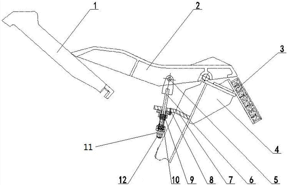
[0016] Such as figure 1 As shown, a rear grate piece tensioning device of a garbage incinerator includes a tie rod 6, a moving grate piece 1, a rear grate piece 2 and a grate support 4, the grate support 4 is provided with a rear grate attachment 3, the The end of the grate support 4 is provided with a fixed block 7, the pull rod 6 passes through the fixed block 7 and is connected to the rear grate piece 2, and the rear grate piece 2 compresses the moving grate piece 1, and the pull rod 6 is provided with a compression adjustment mechanism for pulling the rear grate sheet 2 to compress the movable grate sheet 1, and the pull rod 6 can be pulled by the compression adjustment mechanism to control the rear grate sheet 2 to compress the movable grate sheet 1.
[0017] Such as figure 1 As shown, the compression adjustment mechanism includes a spring 9 and an adjustment nut 11. The head of the pull rod 6 is connected to the rear grate plate 2, and the tail of the pull rod 6 is threadedly connected to the adjustment nut 11. The spring 9 is sleeved on the pull rod 6, and the spring 9 is sandwiched between the adjusting nut 11 and the fixing block 7. The adjusting nut 11 and the spring 9 can be used to control the pull rod 6, thereby controlling the rear grate plate 2. Press the moving grate piece 1.
[0018] Such as figure 1 As shown, the spring 9 is connected with a spring sleeve 10.
[0019] Such as figure 1 As shown, the tail of the pull rod 6 is threadedly connected with a lock nut 12, and the adjustment nut 11 is located between the spring 9 and the lock nut 12. The adjustment nut 11 can be locked by the lock nut 12 to prevent loosening .
[0020] Such as figure 1 As shown, the head of the pull rod 6 and the rear grate piece 2 are connected by a pin 5.
[0021] Such as figure 1 As shown, the fixed block 7 is provided with a positioning pin 8 which is connected to the pull rod 6 and the positioning pin 8 can be used to provide positioning assistance.
[0022] Such as figure 1 As shown, the positioning pin 8 and the pull rod 6 are connected by a gasket.
[0023] Such as figure 1 As shown, the fixing block 7 is provided with a guide hole, and the pull rod 6 passes through the guide hole.
[0024] The present invention also provides a garbage incinerator, which includes the back grate piece tensioning device of the garbage incinerator described in any one of the above.
[0025] The present invention provides a rear grate piece tensioning device of a waste incinerator and a waste incinerator. The pressing force of the rear grate piece 2 on the moving grate piece 1 can be realized by rotating the adjusting nut 11 and compressing the spring 9, and then locking The nut 12 is locked to prevent changes in the compression force. The compression adjustment mechanism is used to adjust the degree to which the rear grate sheet 2 is pressed against the movable grate sheet 1 through the tie rod 6, which can effectively prevent the rear grate sheet 2 from turning over and leaving the furnace during the operation of the incinerator Row bracket 4, fall into the slag well.
[0026] The back grate piece tensioning device of the garbage incinerator provided by the present invention and the garbage incinerator have the following advantages:
[0027] 1) Simple structure, easy processing, convenient installation, no maintenance or maintenance.
[0028] 2) Under the same working environment, it can effectively prevent the grate piece 2 from turning over and leaving the grate support and falling into the slag trap after the incinerator is in operation.
[0029] 3) The use of spring tension, simple structure, can effectively adjust the pressing force of the back grate piece 2 to the moving grate piece 1, keep the friction surface of the moving grate piece 1 and the static grate piece close to each other and make the friction resistance of the friction surface Moderate, reduce the power of the hydraulic drive system and extend the service life of the grate piece.
[0030] 4) Reduced the phenomenon that the rear grate piece 2 separated from the grate support 4 and fell into the slag pit; there is no metal block or other hardware falling into the friction surface, the end of the rear grate piece 2 wears evenly and smoothly, and does not affect the continuous operation of the grate piece ; Effectively improve the installation structure of the rear grate piece 2, which not only extends the service life of the equipment, reduces maintenance costs, and greatly improves the economic benefits of the enterprise.
[0031] The above content is a further detailed description of the present invention in conjunction with specific preferred embodiments, and it cannot be considered that the specific implementation of the present invention is limited to these descriptions. For those of ordinary skill in the technical field to which the present invention belongs, a number of simple deductions or substitutions can be made without departing from the concept of the present invention, which should be regarded as falling within the protection scope of the present invention.

PUM

no PUM

Description & Claims & Application Information

We can also present the details of the Description, Claims and Application information to help users get a comprehensive understanding of the technical details of the patent, such as background art, summary of invention, brief description of drawings, description of embodiments, and other original content. On the other hand, users can also determine the specific scope of protection of the technology through the list of claims; as well as understand the changes in the life cycle of the technology with the presentation of the patent timeline. Login to view more.
Why Eureka
Try Eureka