
Shock absorption type microhole punching mold

A technology of stamping dies and micro holes, which is applied in the field of stamping dies, can solve the problems affecting the processing accuracy, the displacement of the lower die, the eccentricity of punching holes, etc., and achieve the effects of improving precision, slowing down direct impact force and improving stability

Inactive Publication Date: 2017-10-10
昆山钣源冲压技术有限公司
View PDF5 Cites 2 Cited by
  • Summary
  • Abstract
  • Description
  • Claims
  • Application Information

AI Technical Summary

Problems solved by technology

[0003] Our common stamping dies generally apply the punch of the upper die directly to the lower die. In this way, the punch of the upper die will have a great impact and vibration on the lower die and the lower die seat. Such vibration is easy to occur on the lower die when punching. The displacement causes the punching to appear eccentric, which affects the processing accuracy

Method used


Image

  • Shock absorption type microhole punching mold
  • Shock absorption type microhole punching mold

Examples


Embodiment Construction

[0017] The following will clearly and completely describe the technical solutions in the embodiments of the present invention with reference to the accompanying drawings in the embodiments of the present invention. Obviously, the described embodiments are only some, not all, embodiments of the present invention.

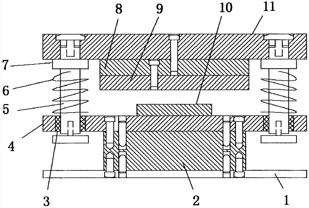
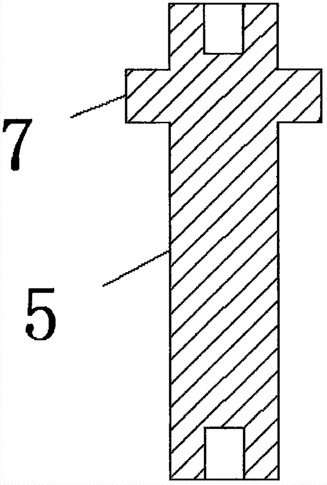
[0018] refer to Figure 1-2 , a shock-absorbing microporous stamping die, including a base plate 1, a support base 2 is installed above the base plate 1, a lower mold base 4 is installed above the support base 2, and mounting holes are opened on both ends of the upper end of the lower mold base 4 , a guide sleeve 3 is fixedly installed in the mounting hole, a lower mold 10 is installed above the lower mold base 4, a top plate 11 is arranged above the lower mold 10, an upper mold base 8 is installed on the bottom of the top plate 11, and the bottom of the upper mold base 8 An upper mold 9 is installed, and the upper mold 9 is located directly above the lower mold 10. ...


PUM


Abstract

The invention discloses a shock absorption type microhole punching mold which comprises a bottom plate. A supporting seat is mounted on the upper portion of the bottom plate. A lower mold seat is mounted on the upper portion of the supporting seat. Mounting holes are formed in the two ends of the upper portion of the lower mold seat. A guide sleeve is fixedly mounted in each mounting hole. A lower mold is mounted on the upper portion of the lower mold seat. An ejector plate is arranged on the upper portion of the lower mold. An upper mold seat is mounted at the bottom of the ejector plate. An upper mold is mounted at the bottom of the upper mold seat and located over the lower mold. Through holes are formed in the two ends of the top of the ejector plate. A guide column is connected in each through hole in a sleeved manner. An annular limiting shoulder table is arranged on the column segment of each guide column. Each guide column and the corresponding limiting shoulder table are of an integrated structure. A locking screw is mounted at the top end of each guide column. Each guide column and the ejector plate are in fastening connection through the corresponding locking screw. Each guide column is connected with a spring in a sleeved manner. According to the shock absorption type microhole punching mold, stability in the punching process and punching precision are improved.

Description

technical field [0001] The invention relates to the technical field of stamping dies, in particular to a shock-absorbing microporous stamping die. Background technique [0002] Stamping die is a special process equipment for processing materials (metal or non-metal) into parts (or semi-finished products) in cold stamping processing, called cold stamping die (commonly known as cold stamping die). Stamping is a pressure processing method that uses a mold installed on a press to apply pressure to the material at room temperature to cause separation or plastic deformation to obtain the required parts. [0003] Our common stamping dies generally apply the punch of the upper die directly to the lower die. In this way, the punch of the upper die will have a great impact and vibration on the lower die and the lower die seat. Such vibration is easy to occur on the lower die when punching. The displacement causes the phenomenon of eccentric punching, which affects the precision of pr...

Claims


Application Information

Patent Timeline
IPC IPC(8): B21D28/34B26F1/14F16F15/067
CPCB21D28/34B26F1/14F16F15/067
Inventor 宋功艮
Owner 昆山钣源冲压技术有限公司
Features
  • Generate Ideas
  • Intellectual Property
  • Life Sciences
  • Materials
  • Tech Scout
  • Unparalleled Data Quality
  • Higher Quality Content
  • 60% Fewer Hallucinations
Learn More