Supercharge Your Innovation With Domain-Expert AI Agents!

Copper electroplating solution, method for electroplating copper and method for forming copper cylinder

A copper electroplating solution and copper electroplating technology, applied in the field of copper electroplating solution, can solve the problems of increasing electroplating time and improving electroplating effect

Inactive Publication Date: 2017-11-07
TAIWAN ADVANCED SYST CORP
View PDF7 Cites 0 Cited by
  • Summary
  • Abstract
  • Description
  • Claims
  • Application Information

AI Technical Summary

Problems solved by technology

However, this method increases the plating time
[0008] In addition, in the prior art, there is no relevant literature on improving the electroplating effect by reducing the copper grain size.

Method used


Image

  • Copper electroplating solution, method for electroplating copper and method for forming copper cylinder
  • Copper electroplating solution, method for electroplating copper and method for forming copper cylinder
  • Copper electroplating solution, method for electroplating copper and method for forming copper cylinder

Examples


Embodiment 1

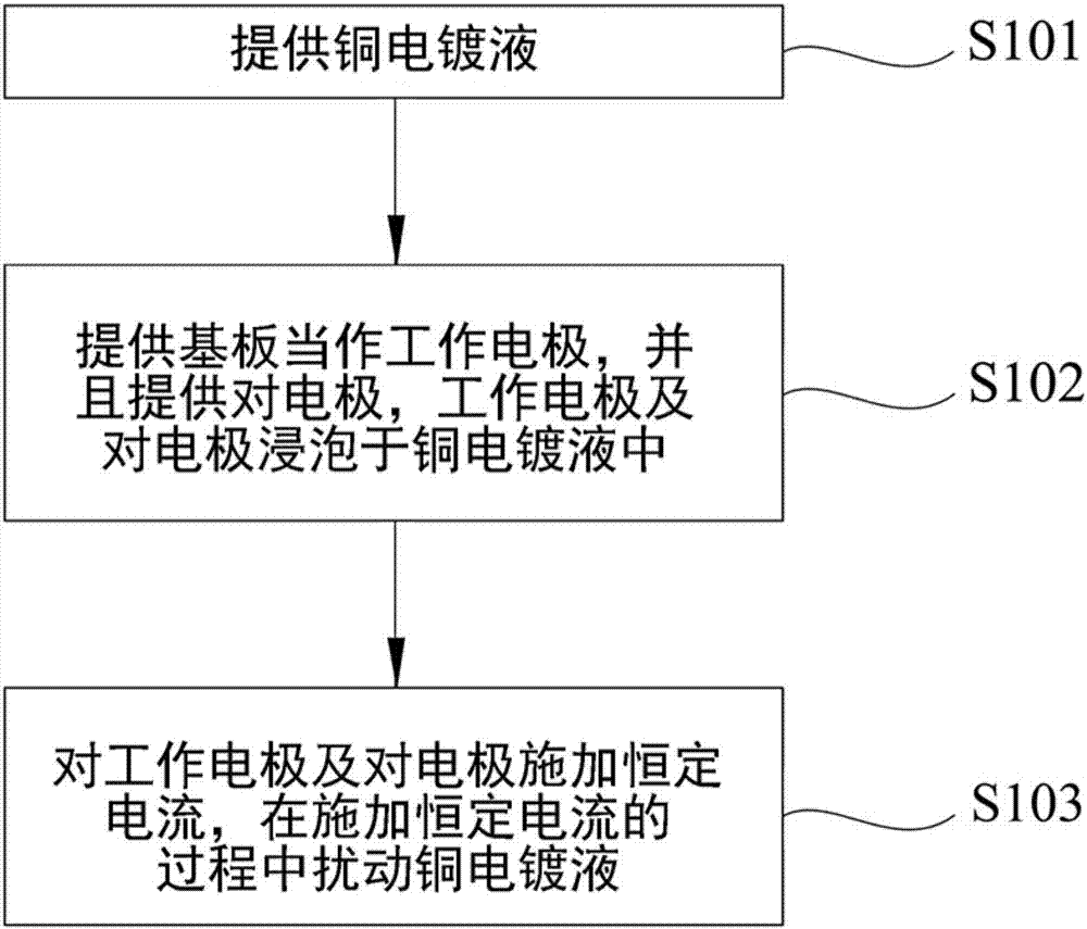
[0064] to accompany figure 1 And provide copper electroplating solution with reference to the concentration in Table 1 (sorted out at the end of the specification), and place the prepared copper electroplating solution in the electroplating tank of the electroplating equipment (step S101). Copper electroplating baths consist of the following concentrations of substances:

[0065] 1.2×10 5 ppmCuSO 4 ·5H 2 O;

[0066] 1.176×10 5 ppm of H 2 SO 4 ;

[0067] 60ppm Cl - ;

[0068] 6ppm SPS;

[0069] PEG 20000 at 240ppm; and

[0070] JGB, so that the concentration ratio of JGB:PEG 20000 is 1:40000.

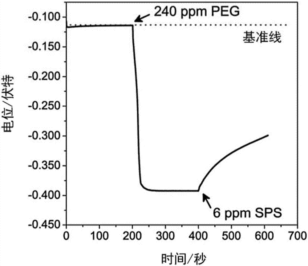
[0071] In order to observe the effect of SPS and PEG on the plating potential during the following electroplating, so as to understand their roles in electroplating. Therefore, in this example, PEG 20000 and SPS were added sequentially when the current was applied. In other embodiments, SPS and PEG 20000 have been added to the copper electroplating solution before electropl...

Embodiment 2-16

[0077] Electroplating was performed in the same manner as in Example 1, the difference being that the added concentrations of SPS and PEG 20000 are shown in Table 1. After the electroplating is completed, the observation results on the surface of the copper film layer are also presented in the Figure 4 , Figure 5 middle.

Embodiment 17

[0079] Electroplating was performed in the same manner as in Example 1, except that the concentrations of SPS and PEG 20000, and the current density are shown in Table 1. After the electroplating is completed, the observation results on the surface of the copper film layer show Figure 6 , Figure 7 middle.


PUM


Abstract

The invention relates to a copper electroplating solution, a method for electroplating copper and a method for forming a copper cylinder. The copper electroplating solution is characterized in that polyethylene glycol with the molecular mass of 20000 is used as an inhabitor, and the concentration of the polyethylene glycol and the concentration of disulfodipropane sulfonate are optimized. When the copper electroplating solution is used for electroplating, a copper film layer bright like a mirror can be formed on a substrate at high current density. Similarly, when the copper electroplating solution is utilized to form the copper cylinder on the substrate, the quality of the copper cylinder can be improved.

Description

technical field [0001] The invention relates to an electroplating solution, and in particular to a copper electroplating solution, a method for electroplating copper by using the copper electroplating solution, and a method for forming copper pillars on a substrate by using the copper electroplating solution. Background technique [0002] Copper electroplating technology is widely used in the manufacture of ultra-large-scale integration (ultra-large-scale integration, ULSI) semiconductor equipment and copper pillars or lines of printed circuit boards (printed circuit boards, PCBs). [0003] Traditional multi-layer PCBs are limited by their packaging density and cannot meet the trend of advanced products. In order to increase the packaging density, a high-density interconnection (HDI) design using micro-bumps to connect two conductive layers is indispensable. In recent years, due to the superior performance of copper pillars in good pitch, fine pitch capability, and low resi...

Claims


Application Information

Patent Timeline
Patent Type & Authority Applications(China)
IPC IPC(8): C25D3/38C25D5/02
CPCC25D3/38C25D5/022
Inventor 王彦智杨家荣洪俊雄
Owner TAIWAN ADVANCED SYST CORP
Features
  • R&D
  • Intellectual Property
  • Life Sciences
  • Materials
  • Tech Scout
  • Unparalleled Data Quality
  • Higher Quality Content
  • 60% Fewer Hallucinations
Learn More