Module type heat exchanger utilizing suspension and special sealing structure and assembly method

A sealed structure, modular technology, applied in the direction of heat exchanger shell, indirect heat exchanger, heat exchanger type, etc., can solve the problems of different thermal expansion coefficient, heating surface falling off, difficult sealing, etc., to avoid thermal expansion cracking problems, improved safety and tightness, improved maintenance efficiency

Inactive Publication Date: 2017-11-10
山东恒涛节能环保有限公司
View PDF0 Cites 2 Cited by
  • Summary
  • Abstract
  • Description
  • Claims
  • Application Information

AI Technical Summary

Problems solved by technology

[0002] Modular heat exchangers are widely used because they can reduce the amount of work on site and are easy to install and overhaul. Since the modular heat exchanger needs to consider hoisting and transportation rigidity, in order to ensure its structural strength, its heat exchange surface is generally the same as that of the heat exchanger. The frame is welded and fixed, and once the modular heat exchanger is installed and put into operation, the equipment will run for a long time. Due to the difference in expansion coefficient between the heating surface and the frame, the heating surface will be swayed periodically by the flue gas, resu

Method used


Image

  • Module type heat exchanger utilizing suspension and special sealing structure and assembly method
  • Module type heat exchanger utilizing suspension and special sealing structure and assembly method
  • Module type heat exchanger utilizing suspension and special sealing structure and assembly method

Examples


Example Embodiment

[0046] In order to facilitate the understanding of those skilled in the art, the present invention will be further described with reference to the accompanying drawings.

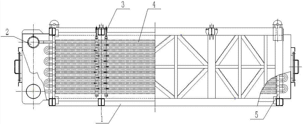
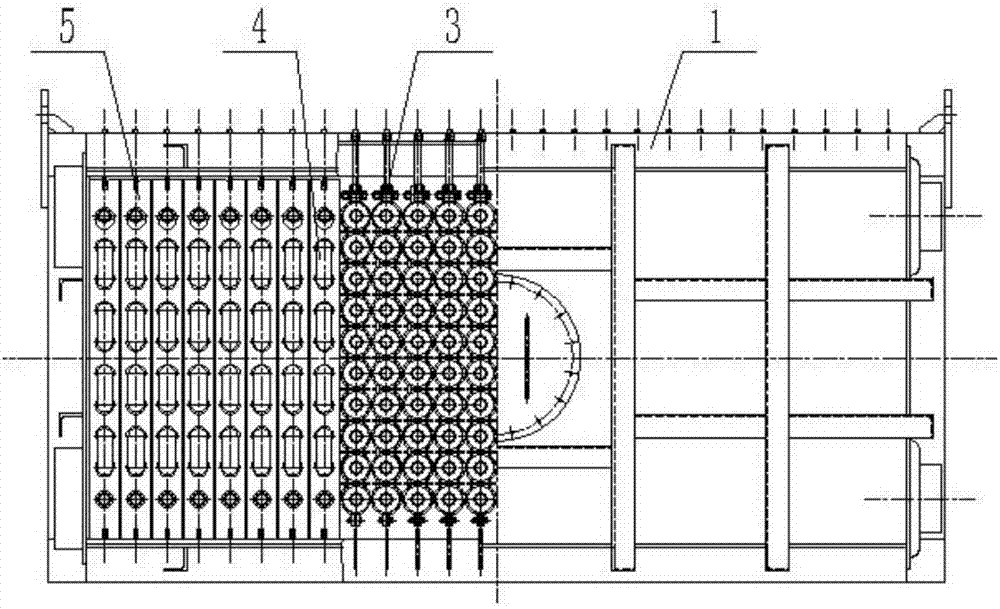
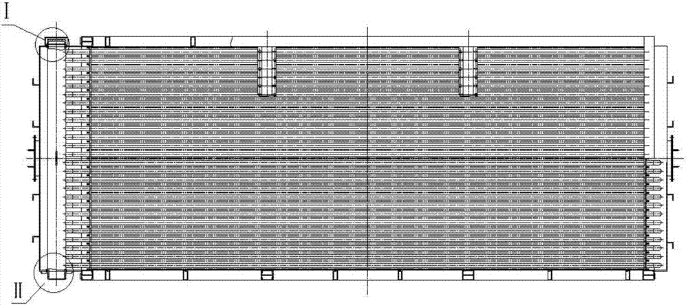
[0047] Such as Figure 1 to Figure 3 As shown, a modular heat exchanger using a hanging and a special sealing structure includes a shell 1. A number of lifting lugs 12 are provided on the top of the shell 1. The shell 1 includes a frame welded by beams. The length deviation of the diagonal line shall not be greater than 7mm, and the joints of the section steel constituting the beam shall be welded firmly, such as Picture 10 As shown, a number of heat exchange tube groups 4 are arranged inside the shell 1, one end of the heat exchange tube group 4 is provided with a header device 2, the heat exchange tube group 4 is provided with a hanging device 3 for hanging, and both ends of the heat exchange tube group 4 With support plate 5 support, such as Figure 15 to Figure 17 As shown, the supporting plate 5 of the pre...


PUM


Abstract

The invention discloses a modular heat exchanger with a hanging and special sealing structure and an assembly method, which belongs to the field of heat exchanger structure, and includes a shell, a plurality of heat exchange tube groups are arranged in the shell, and one end of the heat exchange tube group is There is a header device, the heat exchange tube group is equipped with a hanging device for hanging, and the two ends of the heat exchange tube group are supported by support plates; there are several hanging beams on the top of the shell, and there are a row of hanging beams on both sides of the bottom of each hanging beam. As for the hanging device, a positioning structure is arranged on the upper and lower beams at both ends of the shell, and the positioning structure positions the support plate. The hanging device of the present invention includes two clamping horses, and the two clamping horses face each other to form several buckle cavities, and the two clamping horses clamp the heat exchange tube group through the buckle cavities, and the two ends of the clamping horses are respectively provided with top bolts and bottom bolts to ensure the clamping There is also a clamping plate between each buckle cavity, which assists in clamping the clamping horse. A hanging block is arranged above the top bolt of the hanging device, and a stud bolt is arranged on the top of the hanging block, and the stud bolt is connected with the hanging beam, and the heat exchange tube group is hung on the hanging beam through the hanging device.

Description

technical field [0001] The invention relates to the field of heat exchanger structure, in particular to a modular heat exchanger and an assembly method using a hanging and special sealing structure. Background technique [0002] Modular heat exchangers are widely used because they can reduce the amount of work on site and are easy to install and overhaul. Since the modular heat exchanger needs to consider hoisting and transportation rigidity, in order to ensure its structural strength, its heat exchange surface is generally the same as that of the heat exchanger. The frame is welded and fixed, and once the modular heat exchanger is installed and put into operation, the equipment will run for a long time. Due to the difference in expansion coefficient between the heating surface and the frame, the heating surface will be swayed periodically by the flue gas, resulting in the heating surface and the frame. Fatigue cracks appear in the welds between the frames, and finally the h...

Claims


Application Information

Patent Timeline
IPC IPC(8): F28D7/08F28F9/013F28F9/18F28F11/00B23P21/00
CPCF28D7/082B23P21/00F28F9/013F28F9/18F28F11/00F28F2230/00F28F2275/06
Inventor 方夕涛崔乃星王艳丽隋鹏林
Owner 山东恒涛节能环保有限公司
Why Eureka
Try Eureka