Cell particle detection method based on direct current electric impedance measurement

A technology of impedance measurement and particle detection, which is applied in the field of blood cell analysis, can solve problems such as complex problems, indiscrimination, and number errors, and achieve the effects of accurate judgment, wide application, and accurate measurement

Inactive Publication Date: 2017-11-21
上海纳衍生物科技有限公司
View PDF9 Cites 3 Cited by
  • Summary
  • Abstract
  • Description
  • Claims
  • Application Information

AI Technical Summary

Problems solved by technology

[0009] 2) Overlap phenomenon (number error)
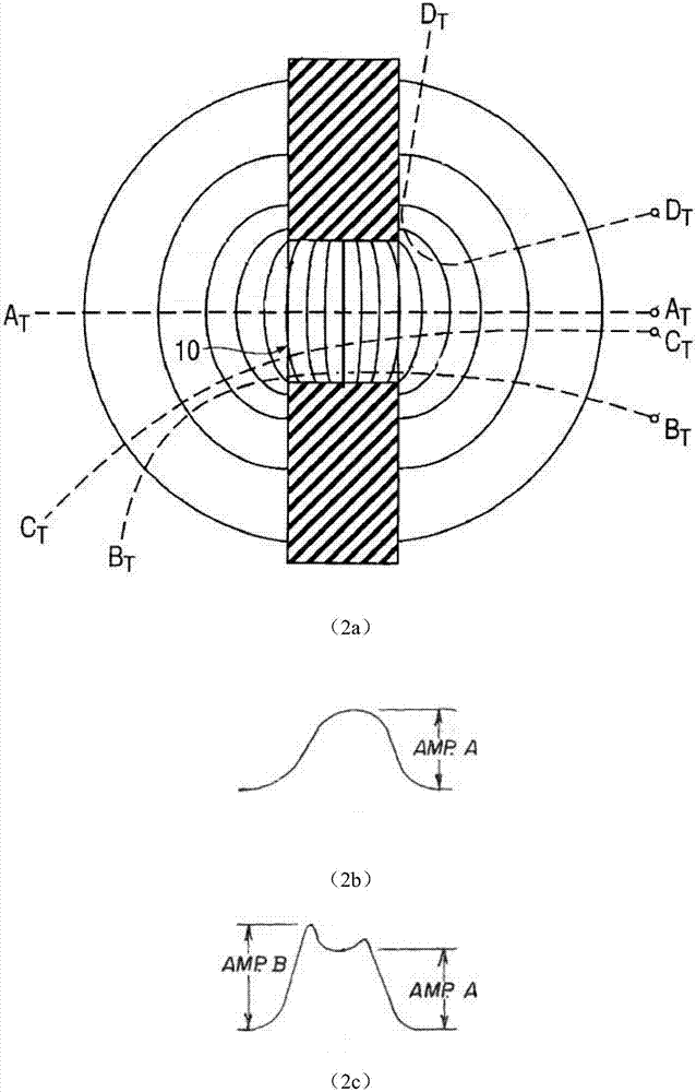
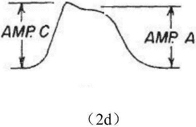
[0015] The above describes the phenomena of particles under the influence of trajectory and overlap, but in actual situations, these two situations will occur at the same time, making the problem very complicated, such as M-shaped signals, these two situations The waveforms exhibited are basically similar to
[0016] At prese

Method used


Image

  • Cell particle detection method based on direct current electric impedance measurement
  • Cell particle detection method based on direct current electric impedance measurement
  • Cell particle detection method based on direct current electric impedance measurement

Examples


Example Embodiment

[0060] Examples:

[0061] At the beginning of the analysis test, the pulse signal is sent from the front sensor to the signal processing part, combined with differentiation, integration, peak detection and other methods, the pulse width, multi-peak number, peak value and valley value of the pulse signal are calculated by the hardware circuit. The principle is as follows Image 6 Shown.

[0062] Threshold level: set according to the actual situation to intercept noise and debris signals, such as Figure 4 Shown in Vth.

[0063] Pulse width measurement circuit: compare the input pulse signal, whether it is a single-peak signal generated by a single particle or a multi-peak / M-shaped signal generated by multiple particles, with the set threshold level, and the part that exceeds the threshold level Measure the time width to get the pulse width information of the pulse signal, such as Figure 4 Shown in Tw.

[0064] Peak and valley measurement circuit: compare the input pulse signal, whethe...

Example Embodiment

[0079] Example 2:

[0080] At the beginning of the analysis test, the pulse signal is sent from the front sensor to the signal processing part. The pulse signal is converted into a digital quantity after digitization and sampling, and then sent to the computer. The pulse width, the number of multiple peaks, the peak value and the valley of the pulse signal are calculated by the digital algorithm. Value and other measurement information, the principle is as Figure 8 Shown.

[0081] The computer stores the pulse width, multiple peaks, peaks and valleys of all these pulse signals.

[0082] After the analysis test is over, the computer performs statistical processing on all pulse information.

[0083] The computer calculates the average value of the pulse width of all single-peak pulse signals. The pulse width distribution of the single-peak pulse signal is as follows: Picture 9 As shown, after setting the window width as needed and performing moving average processing, the highest val...


PUM


Abstract

The present invention relates to a cell particle detection method based on direct current electric impedance measurement, wherein the cell particle detection method is used for detecting the volume and the number of cell particles, and comprises: 1) obtaining the pulse signal of cell particles to be detected by using a direct current electric impedance method; 2) obtaining the waveform pulse width, the multi-peak condition, the peak value and the valley value of the pulse signal; and 3) setting the threshold value of the pulse width, judging whether the pulse signal is a single-particle pulse signal or a multi-particle pulse signal according to the pulse width and the multi-peak condition, counting the cell particles, and obtaining the real volume of the cell particles according to the peak value and the valley value of the pulse signal. Compared to the method in the prior art, the method of the present invention has advantages of accurate judgment, wide application and the like.

Description

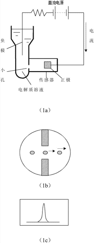
technical field [0001] The invention relates to the field of blood cell analysis, in particular to a cell particle detection method based on direct current electrical impedance measurement. Background technique [0002] In the field of blood cell analysis, DC electrical impedance method is currently the most commonly used method for RBC / PLT (red blood cell / platelet) measurement. figure 1 It is a simple schematic diagram of direct current impedance measurement, and the cell suspension to be tested isolated in two containers is connected through a small hole. The two measuring electrodes are respectively located in the two containers, and the electric field is established in the small hole through the excitation of the DC source. Driven by pressure, the particles or cells flowing through the small hole will cause changes in electrical impedance, which will generate pulse signals one by one. Ideally, one particle corresponds to one pulse, the number of pulses indicates the nu...

Claims


Application Information

Patent Timeline
IPC IPC(8): G01N15/10
CPCG01N15/1031G01N2015/0065G01N2015/1006G01N2015/1087
Inventor 陶靖
Owner 上海纳衍生物科技有限公司
Why Eureka
Try Eureka