Cylinder tank for copper bar tinning and full-automatic copper bar tinning production device and method

A production equipment, fully automatic technology, applied in the direction of plating tank, electrolysis process, electrolysis components, etc., can solve the problems of high energy consumption, decreased electroplating efficiency, product quality decline, etc., to avoid cross-contamination and reduce energy consumption.

Pending Publication Date: 2017-11-24
ZHAOQING CITY ZHONGNANTIAN IND CO LTD
View PDF10 Cites 4 Cited by
  • Summary
  • Abstract
  • Description
  • Claims
  • Application Information

AI Technical Summary

Problems solved by technology

[0002] At present, there are two traditional tinning methods: 1. Using the rack plating method, the copper discharge is placed in the tinning bath with a rack for tinning. Because the conductive point is fixed, the contact point will increase with the extension of the plating time. , the temperature rises gradually, so that the electroplating efficiency gradually decreases; all tanks of this process are in an open state, and the generated acid and alkali mist cannot be sealed and collected, which seriously affects the environment; during the transition of each process, the loss of the bath liquid is large, and the hanger is exposed Some parts will be plated with tin, which wastes some raw materials and has hanger loss
[0003] 2. Although the method of continuous tinning of copper bars solves some of the defects of the above-mentioned traditional tin plating, it still has the following disadvantages: there is no device for removing residual chemical liquid between each process, so the amount of chemical liquid is large and wasteful; use spray cleaning , because the nozzle is a single water outlet, the cleaning is not thorough due to the influence of the atomization degree and angle of the nozzle cleaning water, etc., because there is a lot of residual

Method used


Image

  • Cylinder tank for copper bar tinning and full-automatic copper bar tinning production device and method
  • Cylinder tank for copper bar tinning and full-automatic copper bar tinning production device and method
  • Cylinder tank for copper bar tinning and full-automatic copper bar tinning production device and method

Examples


Example Embodiment

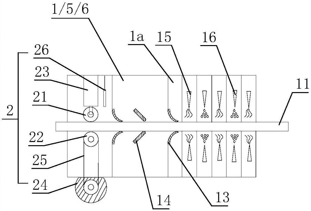
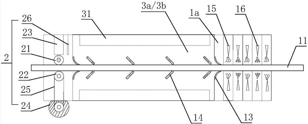
[0030] Such as Figure 1 to 7 As shown, the cylinder tank for tinning copper bars of the present invention is provided with a conveying channel for conveying the copper bar 11 in the longitudinal direction of the cylinder tank 1, a plurality of horizontal supporting pulleys 12 are provided at the lower part of the conveying channel, and a conveying device 2 is provided at the front feeding part. , Is characterized in that: the cylinder tank 1 is provided with front and rear baffle groups 13, and the front and rear baffle groups 13 are provided with guide plates 14 between the baffle groups 13 and the guide plates 14 along the horizontal conveying channel. The left and right sides are arranged in a "V" shape. The rear discharge part of the cylinder tank 1 is provided with a sub-tank 1a. In the sub-tank 1a, a left and right air knife 15 and a cleaning water knife 16 are arranged along the horizontal conveying channel.

[0031] The opening distance of the guide plate 14 is gradually...


PUM


Abstract

The invention discloses a cylinder tank for copper bar tinning. The cylinder tank is longitudinally provided with a conveying channel for conveying a copper bar, multiple horizontal supporting pulleys are arranged on the lower portion of the conveying channel, a front side feeding part is provided with a conveying device, water fender sets on the front portion and the rear portion are arranged in the cylinder tank, a guide plate is arranged between the water fender sets on the front portion and the rear portion, the water fender sets and the guide plate are arranged in a left-and-right opposite manner to form a V shape along the horizontal conveying channel, the rear side discharging part of the cylinder tank is provided with a sub groove, and a wind knife and a cleaning water knife which are opposite in left and right are arranged in the sub groove along the horizontal conveying channel. A full-automatic copper bar tinning production device comprises an ultrasonic wave oil removal groove, an electrolysis oil removal groove, an activation groove, an electroplating groove, a passivation groove and a hot water ultrasonic wave cleaning groove which are sequentially arranged along the conveying channel.

Description

technical field [0001] The invention belongs to the field of electroplating, and in particular relates to a cylinder tank for tinning copper bars, a cleaning tank, an electroplating tank, an activation and passivation tank, and fully automatic tinning production equipment for copper bars. Background technique [0002] At present, there are two traditional tinning methods: 1. Using the rack plating method, the copper discharge is placed in the tinning bath with a rack for tinning. Because the conductive point is fixed, the contact point will increase with the extension of the plating time. , the temperature rises gradually, so that the electroplating efficiency gradually decreases; all tanks of this process are in an open state, and the generated acid and alkali mist cannot be sealed and collected, which seriously affects the environment; during the transition of each process, the loss of the bath liquid is large, and the hanger is exposed Some parts will be plated with tin, ...

Claims


Application Information

Patent Timeline
IPC IPC(8): C25D17/02C25D3/30C25D7/00C25D19/00
CPCC25D3/30C25D7/00C25D17/00C25D17/02
Inventor 徐善刚
Owner ZHAOQING CITY ZHONGNANTIAN IND CO LTD
Why Eureka
Try Eureka