Camera lens assembly
A technology of camera lenses and lenses, which is applied in the field of camera lens groups, can solve problems such as unfavorable imaging effects and improvement of product yield restrictions
- Summary
- Abstract
- Description
- Claims
- Application Information
AI Technical Summary
Problems solved by technology
Method used
Image

Examples
Embodiment 1
[0050] First refer to Figure 1 to Figure 5 An imaging lens group according to Embodiment 1 of the present application will be described.
[0051] figure 1 It is a schematic diagram showing the structure of the camera lens group in Embodiment 1. Such as figure 1 As shown, the camera lens group includes 5 lenses. The five lenses are the first lens E1 with object side S1 and image side S2, the second lens E2 with object side S3 and image side S4, the third lens E3 with object side S5 and image side S6, and the third lens E3 with object side S5 and image side S6. A fourth lens E4 with side S7 and image side S8 and a fifth lens E5 with object side S9 and image side S10. The first lens E1 to the fifth lens E5 are sequentially arranged from the object side to the image side of the imaging lens group. The centering group includes a first lens and a second lens, and the fixed group includes a third lens, a fourth lens and a fifth lens. The centering group is adjustable in the di...
Embodiment 2
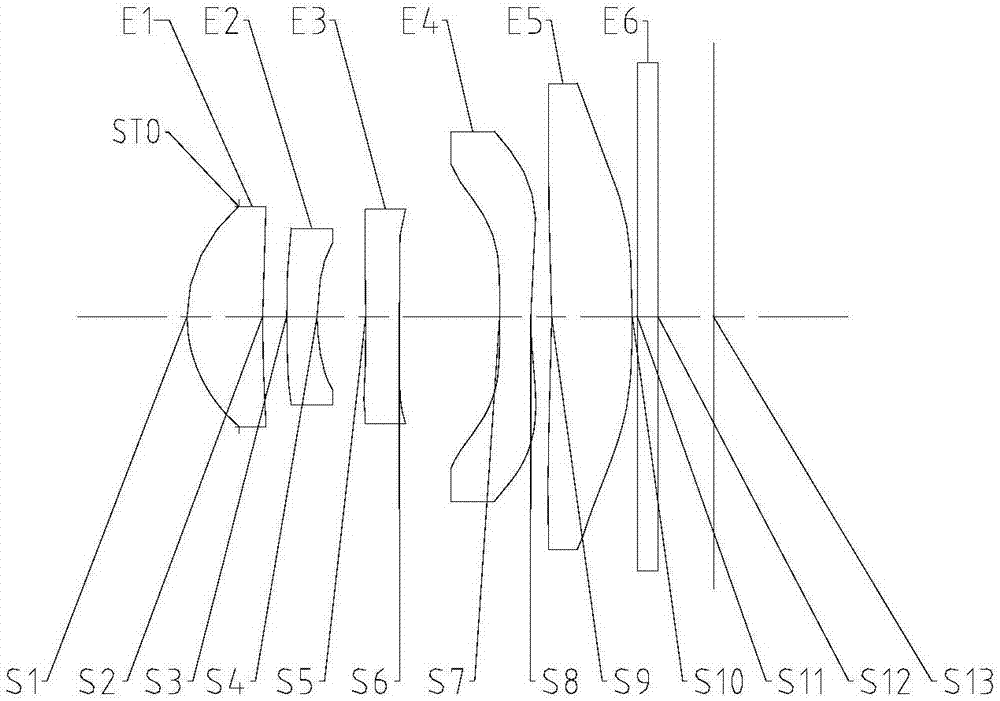
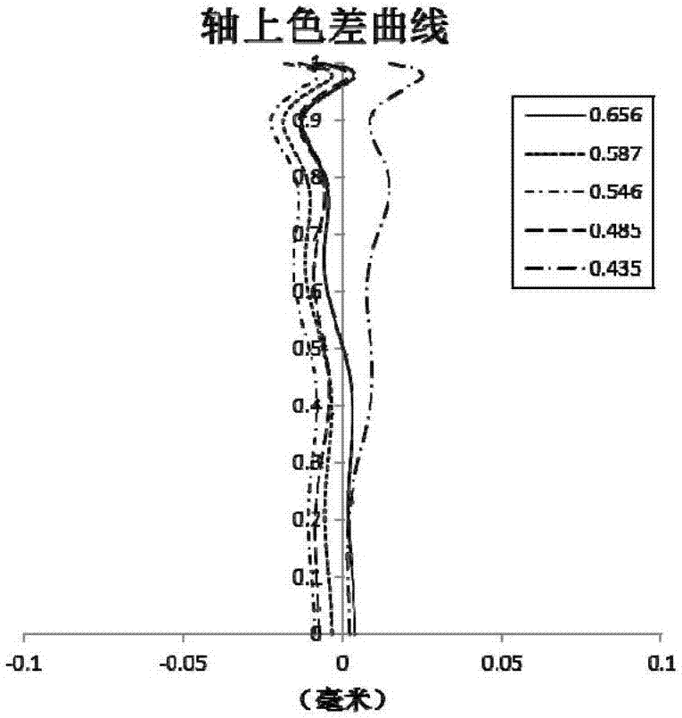
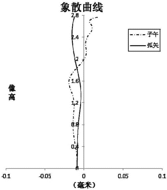
[0073] Refer to the following Figure 6 to Figure 10 An imaging lens group according to Embodiment 2 of the present application will be described.
[0074] Image 6 It is a schematic diagram showing the structure of the camera lens group in Embodiment 2. Such as Image 6 As shown, the camera lens group includes 6 lenses. The six lenses are the first lens E1 with object side S1 and image side S2, the second lens E2 with object side S3 and image side S4, the third lens E3 with object side S5 and image side S6, and the third lens E3 with object side S5 and image side S6. A fourth lens E4 with a side S7 and an image side S8, a fifth lens E5 with an object side S9 and an image side S10, and a sixth lens E6 with an object side S11 and an image side S12. The first lens E1 to the sixth lens E6 are sequentially arranged from the object side to the image side of the imaging lens group. The centering group includes a first lens, a second lens and a third lens, and the fixed group in...
Embodiment 3
[0094] Refer to the following Figure 11 to Figure 15 An imaging lens group according to Embodiment 3 of the present application will be described.
[0095] Figure 11 It is a schematic diagram showing the structure of the camera lens group in Embodiment 3. The camera lens group includes a first lens E1 , a second lens E2 , a third lens E3 , a fourth lens E4 , a fifth lens E5 and a sixth lens E6 from the object side to the image side. The centering group includes a first lens, a second lens and a third lens, and the fixed group includes a fourth lens, a fifth lens and a sixth lens. The centering group is adjustable in the direction perpendicular to the optical axis.
[0096] The first lens E1 may have positive refractive power, and its object side S1 may be convex, and its image side S2 may be concave.
[0097] The second lens E2 may have negative refractive power, and its object side S3 may be convex, and its image side S4 may be concave.
[0098] The third lens E3 may h...
PUM
| Property | Measurement | Unit |
|---|---|---|
| Edge thickness | aaaaa | aaaaa |
Abstract
Description
Claims
Application Information
 - Generate Ideas
- Intellectual Property
- Life Sciences
- Materials
- Tech Scout
- Unparalleled Data Quality
- Higher Quality Content
- 60% Fewer Hallucinations
Browse by: Latest US Patents, China's latest patents, Technical Efficacy Thesaurus, Application Domain, Technology Topic, Popular Technical Reports.
© 2025 PatSnap. All rights reserved.Legal|Privacy policy|Modern Slavery Act Transparency Statement|Sitemap|About US| Contact US: help@patsnap.com