
Nameplate device of electric transmission lines

A technology for transmission lines and nameplates, which is applied to display devices, signs, and illuminated signs. It can solve problems such as difficult to distinguish line names and tower numbers, difficulty in high-altitude operations, and easy corrosion of screws, so as to reduce damage or loss of nameplates. The incidence rate, reduce the difficulty of installation and disassembly, the effect of simple and convenient installation and disassembly

Pending Publication Date: 2017-12-19
FOSHAN POWER SUPPLY BUREAU GUANGDONG POWER GRID
View PDF4 Cites 0 Cited by
  • Summary
  • Abstract
  • Description
  • Claims
  • Application Information

AI Technical Summary

Problems solved by technology

At present, the nameplate device used on the transmission line is mainly made of hard plastic. The mechanical strength of the nameplate is not high, and it is easy to be damaged under the action of external force, and it is easy to qualitatively change, deform or damage under the action of sunlight and saline-alkali corrosion; and , its connection with the tower structure is extremely simple, and it is only fixed on the angle steel or steel frame by simple screws. The stress concentration is obvious at the connection position, and under the washing of rainwater, the screws are easy to rust, and the line nameplate is damaged or lost. Once the nameplate of the line is lost, it is difficult to distinguish the name of the line and the number of the tower. On the other hand, once the nameplate of the line is damaged or lost, the line operation and maintenance personnel need to climb the tower to replace it. It is difficult to work at heights and the disassembly and replacement process is complicated. bring great challenges

Method used


Image

  • Nameplate device of electric transmission lines

Examples


Embodiment Construction

[0012] The accompanying drawings are for illustrative purposes only, and should not be construed as limitations on this patent; in order to better illustrate this embodiment, certain components in the accompanying drawings will be omitted, enlarged or reduced, and do not represent the size of the actual product; for those skilled in the art It is understandable that some well-known structures and descriptions thereof may be omitted in the drawings. The positional relationship described in the drawings is for illustrative purposes only, and should not be construed as a limitation on this patent.

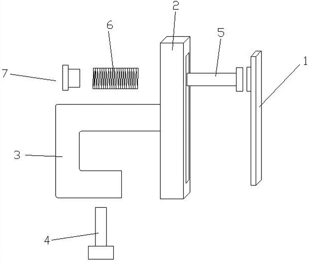
[0013] Such as figure 1 Shown, a kind of transmission line nameplate device comprises: nameplate 1, base 2, also comprise spring pin 5, spring 6, spring pin cap 7, spring pin hole is arranged on described base 2, and described spring pin comprises head and the rod, the head of the spring pin includes magnetic material, the rod of the spring pin passes through the spring pin hole, the...


PUM


Abstract

The invention relates to the technical field of subsidiary facilities for electric transmission lines, in particular to a nameplate device for the electric transmission lines. The nameplate device includes a nameplate, a base, a spring pin, a spring and a spring pin cap, wherein the base is provided with a spring pin hole, the spring pin includes a head part and a rod part, the head part of the spring pin consists of a magnetic material, the rod part of the spring pin penetrates through the spring pin hole, and the head part of the spring pin is clamped on one surface of the base; the rod part of the spring pin is sleeved with the spring after penetrating from one end of the spring pin hole and then fixedly connected with the spring pin cap; the spring pin is fixed to the base, one end of the spring abuts against the base, the other end of the spring abuts against the spring pin cap, and the spring stays in a semi-compression state; since the nameplate is provided with the magnetic material, the magnetic material on the head part of the spring pin attracts a magnetic material on the nameplate, and therefore the nameplate can be fixed. Through the structure of the nameplate device, disassembling and assembling of nameplates can be conducted conveniently, and more convenience is provided for replacement.

Description

technical field [0001] The present invention relates to the technical field of ancillary facilities of power transmission lines, and more particularly, to a nameplate device for power transmission lines. Background technique [0002] With the development of society and economy, the demand for electric energy is increasing year by year, and the mileage of transmission lines is also gradually increasing. The vast transmission lines are bound to have a large number of towers as structural supports, and each base tower will have a transmission line nameplate. At present, the nameplate device used on the transmission line is mainly made of hard plastic. The mechanical strength of the nameplate is not high, and it is easy to be damaged under the action of external force, and it is easy to qualitatively change, deform or damage under the action of sunlight and saline-alkali corrosion; and , its connection with the tower structure is extremely simple, and it is only fixed on the ang...

Claims


Application Information

Patent Timeline
IPC IPC(8): G09F7/06G09F7/08G09F13/00
CPCG09F7/06G09F7/08G09F13/00Y04S10/50
Inventor 张纪宾陈涛洪倪建新郭圣曾懿辉施志民司马学凯王成华黄丰宁小亮
Owner FOSHAN POWER SUPPLY BUREAU GUANGDONG POWER GRID
Features
  • Generate Ideas
  • Intellectual Property
  • Life Sciences
  • Materials
  • Tech Scout
  • Unparalleled Data Quality
  • Higher Quality Content
  • 60% Fewer Hallucinations
Learn More