Boiler chimney capable of recovering smoke gas waste heat

A flue gas waste heat and flue gas heat exchange technology, applied in the field of boiler chimneys, can solve the problems of not having a flue gas waste heat recovery device, environmental heat pollution, dust impurities polluting the atmospheric environment, etc., to avoid thermal pollution, improve thermal efficiency, buffer long time effect

Inactive Publication Date: 2018-01-05
HARBIN JINJING BOILER
View PDF0 Cites 0 Cited by
  • Summary
  • Abstract
  • Description
  • Claims
  • Application Information

AI Technical Summary

Problems solved by technology

The boiler is composed of furnace, furnace wall, drum, chimney and other components. The chimney is an important part of the boiler. During the combustion process of the boiler, the flue gas is discharged through the chimney. In the prior art, there is generally no flue gas waste heat recovery device on the chimney , the waste heat in the flue gas cannot be effectively used, and a large amount of waste heat in the flue gas will cause thermal pollution to the environment, and the dust impurities in the flue gas will also pollute the atmospheric environment

Method used


Image

  • Boiler chimney capable of recovering smoke gas waste heat

Examples


Embodiment 1

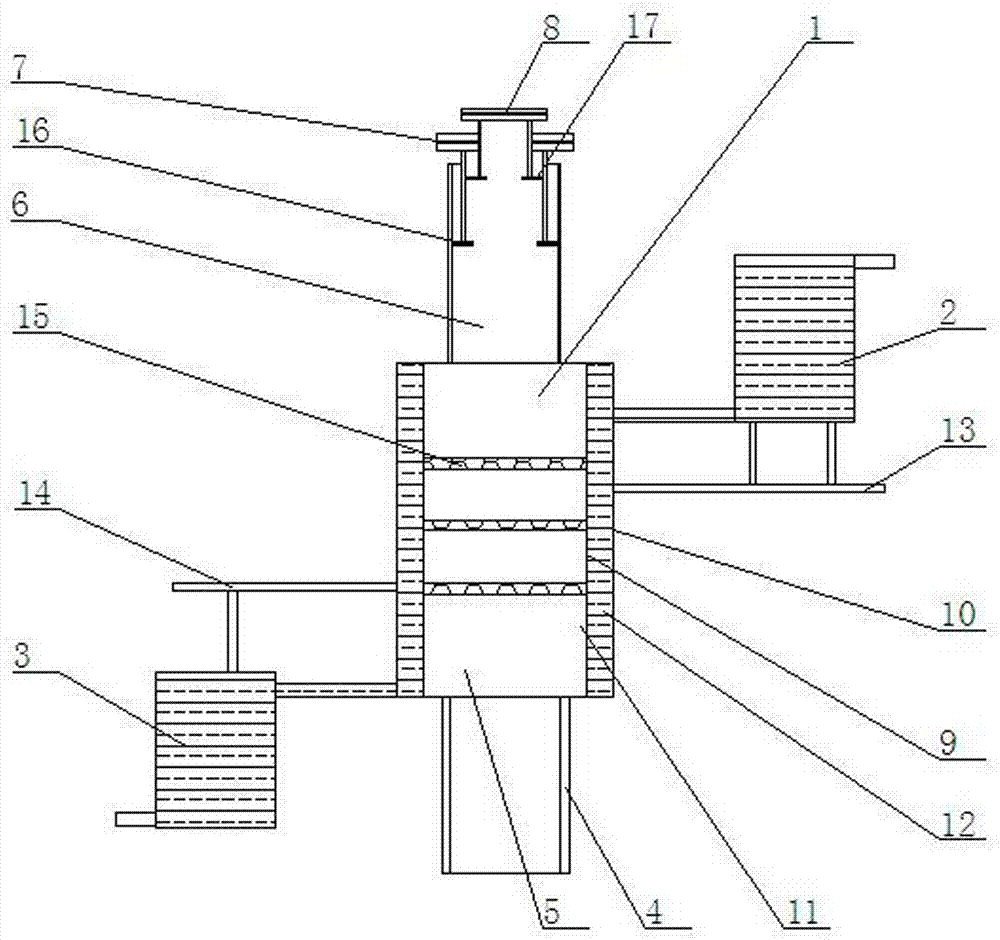
[0014] Such as figure 1 As shown, a boiler chimney that can recover flue gas waste heat includes a chimney body 1, a cold water supply tank 2, and a warm water collection tank 3. 6. A large chimney cover 7 and a small chimney cover 8 are formed. The chimney inlet 4 is welded on the bottom surface of the flue gas heat exchange tube 5, the exhaust tube 6 is welded on the top surface of the flue gas heat exchange tube 5, and the large chimney The cover 7 is installed at the upper end of the exhaust pipe 6, and the small chimney cover 8 is installed at the upper end of the large chimney cover 7; the flue gas heat exchange cylinder 5 is composed of an inner cylinder 9 and an outer cylinder 10, and the outer cylinder 10 is welded On the outer wall of the inner cylinder 9, the inside of the inner cylinder 9 is a smoke chamber 11, and a water exchange chamber 12 is formed between the inner cylinder 9 and the outer cylinder 10; the upper right end of the outer cylinder 10 is install...

Embodiment 2

[0016] Such as figure 1 As shown, the inner cylinder body 9 of the flue gas heat exchange cylinder 5 is equipped with upper and lower three layers of stainless steel metal filter screens 15 .

Embodiment 3

[0018] Such as figure 1 As shown, a large circular metal plate 16 is installed on the inner upper end wall of the exhaust pipe 6, and the large chimney cover 7 is composed of a top cover and a support frame. A circular opening is arranged on the top cover of the large chimney cover 7, and the support The frame is supported on the large circular metal plate 16; the upper end of the internal support frame of the large chimney cover 7 is welded with a small circular metal plate 17, the small chimney cover 8 is composed of a top cover and a support frame, and the bottom of the small chimney cover 8 The end is supported on the small circular metal plate 17 inside the large chimney cover 7 by a support frame.


PUM


Abstract

A boiler chimney capable of recovering flue gas waste heat, comprising a chimney body, a cold water supply tank, and a warm water collection tank. , the chimney inlet tube is welded on the bottom surface of the flue gas heat exchange tube, the exhaust tube is welded on the top surface of the flue gas heat exchange tube, the large chimney cover is installed on the upper end of the smoke exhaust tube, and the small chimney cover is installed on the large chimney Cover the upper end; the flue gas heat exchange cylinder is composed of an inner cylinder and an outer cylinder, and the outer cylinder is welded on the outer wall of the inner cylinder; the upper right end of the outer cylinder is equipped with a first fixing bracket, and the cold water supply The tank is installed on the first fixed frame; the lower left end of the outer cylinder is installed on the second fixed frame, and the warm water collection tank is installed on the second fixed frame. The invention can effectively utilize the residual heat of the flue gas of the boiler to preheat the cold water, effectively utilize the residual heat in the flue gas, improve the thermal efficiency of the boiler, and avoid thermal pollution.

Description

technical field [0001] The invention relates to the field of boiler equipment, in particular to a boiler chimney capable of recovering waste heat of flue gas. Background technique [0002] As a heating equipment commonly used in production and life, boilers are widely used due to their high thermal efficiency. The boiler is composed of furnace, furnace wall, drum, chimney and other components. The chimney is an important part of the boiler. During the combustion process of the boiler, the flue gas is discharged through the chimney. In the prior art, there is generally no flue gas waste heat recovery device on the chimney , the waste heat in the flue gas cannot be effectively used, and a large amount of waste heat in the flue gas will cause thermal pollution to the environment, and the dust impurities in the flue gas will also pollute the atmospheric environment. Contents of the invention [0003] The purpose of the present invention is to provide a boiler chimney tha...

Claims


Application Information

Patent Timeline
Patent Type & Authority Applications(China)
IPC IPC(8): F24H9/00F23J15/02F23J13/08
Inventor 谷哲学
Owner HARBIN JINJING BOILER
Why Eureka
Try Eureka