High precision punching device for printing

A punching device and high-precision technology, which is applied in metal processing and other directions, can solve the problems of printed matter not meeting the process requirements and inaccurate punching, and achieve the effect of avoiding wear and flying

Inactive Publication Date: 2018-01-12
四川省隆昌诚信印务有限公司
View PDF1 Cites 3 Cited by
  • Summary
  • Abstract
  • Description
  • Claims
  • Application Information

AI Technical Summary

Problems solved by technology

[0006] In order to solve the technical problem of inaccurate punching in the printing and binding process, resulting in pr

Method used


Image

  • High precision punching device for printing
  • High precision punching device for printing
  • High precision punching device for printing

Examples


Example Embodiment

[0019] Example 1

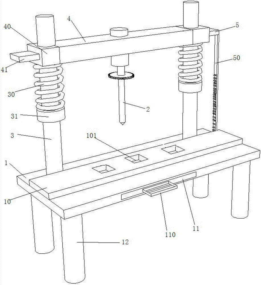
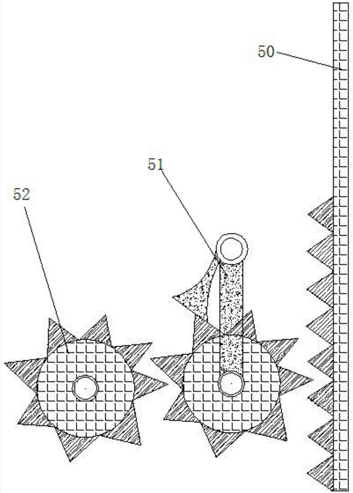
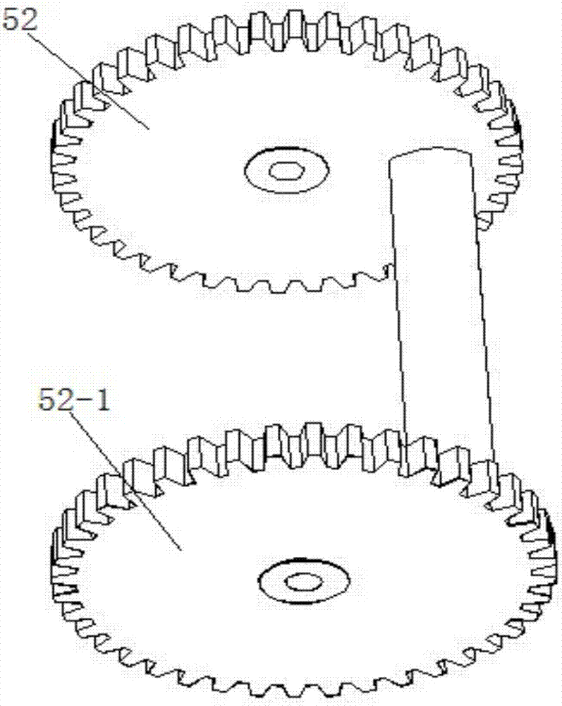
[0020] Such as Figure 1-4 As shown, a high-precision printing and punching device includes a workbench 1, a drill bit, a conveyor belt 10 arranged on the workbench 1, and the conveyor belt 10 is provided with a plurality of punching slots 101; it also includes a workbench 1 The upper support frame 3, the movable plate 4 arranged on the support frame 3; both sides of the movable plate 4 are fixedly installed with fixed rings 40, the two fixed rings 40 are respectively sleeved on the support frame 3, and the support frame 3 is sleeved on A first spring 30 is connected, one end of the first spring 30 is connected with the fixed ring 40, and the other end of the first spring 30 is connected with a limit block 31 fixed on the support frame 3; the outer side of one of the fixed rings 40 is fixedly connected There is a pressing rod 41, and the outer surface of the other fixed ring 40 is fixedly connected with a driving device 5; the driving device 5 includes a first...

Example Embodiment

[0022] Example 2

[0023] Such as figure 2 As shown, on the basis of the high-precision printing and punching device described in Embodiment 1, a paper delivery drawer 11 is arranged inside the worktable 1, and the paper delivery drawer 11 is facing the punching slot 101, and the paper delivery A pull ring 110 is provided on the outer wall of the drawer 11. The setting of the paper delivery drawer 11 can collect the paper scraps generated during the punching process, and prevent the paper scraps from flying around and polluting the workbench.

Example Embodiment

[0024] Example 3

[0025] Further optimized on the basis of the high-precision printing and punching device described in Embodiment 1, the four corners of the bottom end of the worktable 1 are all provided with supporting legs 12. The setting of the support foot stand 12 prevents the bottom surface of the workbench 1 from being worn away, and at the same time, improves the level of the workbench, and prevents the first rack 50 from touching the workbench 1 when it moves down, causing damage to the first rack. .


PUM


Abstract

The invention discloses a high precision punching device for printing. The high precision punching device has the benefits as follows: a driving device performs up-and-down movement along with a movable plate, when the movable plate moves downwards, a first toothed rack moves downwards to drive a ratchet wheel to perform clockwise motion, the ratchet wheel is stopped from moving due to the structural characteristics thereof when performing clockwise motion, so that a conveyor belt does not move, a punching needle performs punching, then the movable plate moves upwards, the first toothed rack moves upwards to drive the ratchet wheel to perform anticlockwise motion, and the conveyor belt moves rightwards for a certain distance; besides, by controlling the up-and-down movement of the movableplate, the punching position is located precisely, a paper scraps collecting drawer is arranged, paper scraps produced during the punching process are collected and prevented from being blown around to contaminate the working table; and moreover, supporting foot rests are arranged, the bottom surface of the working table is prevented from abrasion.

Description

technical field [0001] The invention relates to the technical field of printing machine auxiliary devices, in particular to a high-precision printing punching device. Background technique [0002] Most of the printed matter needs to be bound after printing to meet the convenience of use. Before binding, the printed matter needs to be stacked and aligned for punching. However, the existing technology has the problem of inaccurate punching when punching thicker stacked printed matter. . [0003] In the prior art, there is a punching device for printed matter binding (application number 201610960056.0). In this technical solution, a second fixing plate and a second fixing plate are arranged on the base, and a chute is provided on the upper surface of the base. The bottom of the second fixing plate A slider is provided, and the bone block is slidably connected with the chute, so that the second fixing plate can move back and forth on the base, and it can be adjusted and fixed a...

Claims


Application Information

Patent Timeline
IPC IPC(8): B26F1/16B26D7/18B26D7/00B26D7/01B26D7/06
Inventor 黄绍旭
Owner 四川省隆昌诚信印务有限公司
Why Eureka
Try Eureka