Check patentability & draft patents in minutes with Patsnap Eureka AI!

A high-altitude cable snow removal device

A cable and cylinder technology, which is applied in the field of high-altitude cable snow removal devices, can solve problems such as disconnection, time-consuming and labor-intensive effects, and poor effects, and achieve the effects of easy calculation of height, high degree of automation, and enhanced practicability

Active Publication Date: 2020-01-10
STATE GRID SHANDONG ELECTRIC POWER +1
View PDF6 Cites 0 Cited by
  • Summary
  • Abstract
  • Description
  • Claims
  • Application Information

AI Technical Summary

Problems solved by technology

[0002] At present, cables, as the necessary transmission facilities for people's daily electricity consumption, play an irreplaceable important role. Therefore, it is particularly important to ensure the safe and stable function of the lines. However, snow in winter is easy to deposit on the cables, often Accidents such as disconnection
In the prior art, people usually use long poles to slap the cables in the sky, which is time-consuming and laborious and the effect is not good. It is very inconvenient for snow removal personnel

Method used


Image

  • A high-altitude cable snow removal device
  • A high-altitude cable snow removal device
  • A high-altitude cable snow removal device

Examples


Embodiment 1

[0031] The following is a description of Embodiment 1.

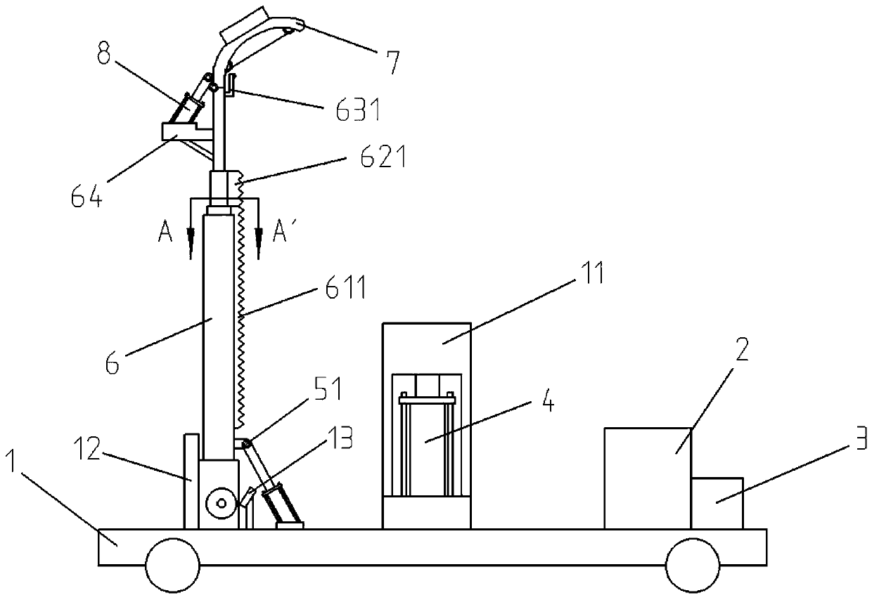
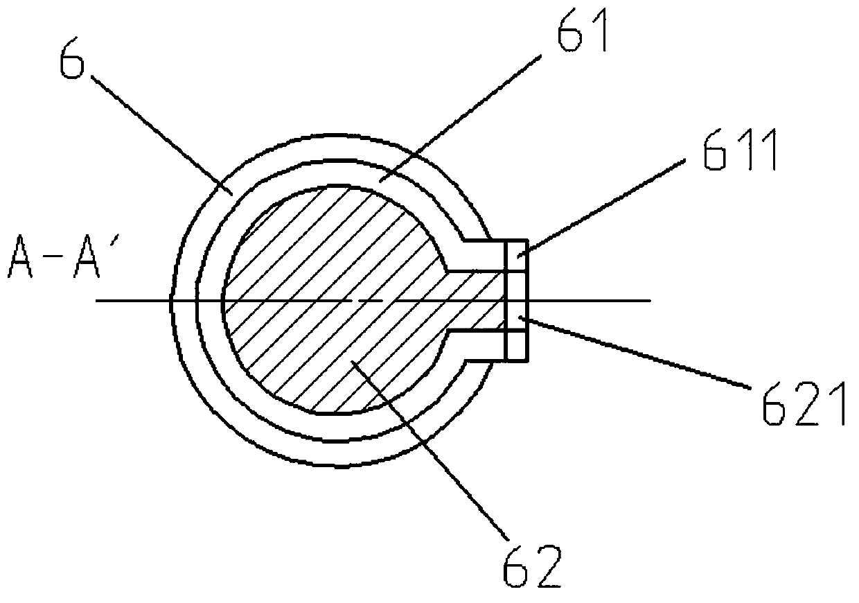
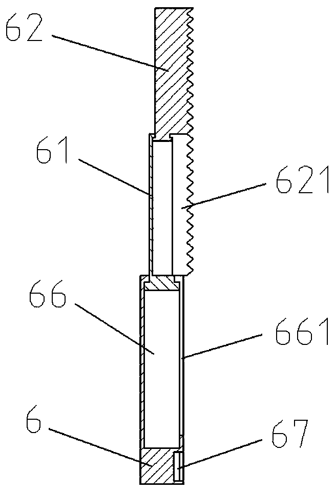
[0032] Such as Figure 1 to Figure 7 As shown, a high-altitude cable snow removal device includes a chassis 1, a protective plate 11, a baffle plate 12, a limit plate 13, a fixing groove 14, a power supply 2, a single-chip microcomputer system 3, a driving cylinder 4, a rotary rod cylinder 5, and a rotary rod Shaft 51, rotating rod slider 52, telescopic bottom rod 6, telescopic middle rod 61, side rack 611, telescopic ejector rod 62, middle rack 621, positioning rod 63, connecting rod 631, infrared sensor 632, cylinder fixing frame 64. Reinforcement rod 65, telescopic rod groove 66, holding notch 661, slide rail groove 67, snow removal body 7, installation block 71, snow removal rope 72, snow removal shaft 73, snow removal cylinder 8, snow removal rod shaft 81, snow removal slider 82. Rotary motor 9, drive gear 91, the bottom of the chassis 1 is provided with rollers, one side of the top is provided with a power supply ...

Embodiment 2

[0036] The following is a description of Embodiment 2.

[0037] In embodiment 2, for the same structure as in embodiment 1, the same symbols are given, and the same description is omitted. Embodiment 2 is improved on the basis of embodiment 1, and the bottom of chassis 1 is provided with a motor and a reducer. The reducer is connected with the roller, and the motor switch is set on the power supply 2, so the degree of automation is higher.

[0038]When the device is in use, after the device is moved to a predetermined position, the power supply 2 is turned on, the switch of the single-chip microcomputer system 3 is turned on, and the cylinder 4 is driven to extend to the maximum thread, and the snow removal cylinder 8 is retracted to drive the snow removal body 7 to turn upwards, and at the same time, the rod cylinder 5 Pull to the shortest thread, the telescopic bottom rod 6 contacts the limit plate 13, and the top side of the middle rack 621 on the telescopic ejector rod 62 ...


PUM


Abstract

The invention discloses a high-altitude cable snow removal device, and belongs to the technical field of circuit snow removal. The high-altitude cable snow removal device comprises a chassis, a rotating rod cylinder, a middle expansion link and a snow removal rotating shaft; a power source and a single-chip machine system are arranged at the top part of the chassis; the power source is connected with the single-chip machine system; a fixed groove is formed in the other side; a driving cylinder is arranged at the center of the top part of the chassis; a revolving motor is arranged at the side part of the top end of the driving cylinder; the revolving motor is connected with a driving gear; a bottom expansion link is connected at the interior of the fixed groove by a shaft; the middle expansion link is provided with a lateral rack; a top expansion link is also arranged in the middle expansion link in a matching manner; the top expansion link is provided with a middle rack; a positioningrod is connected to the top part of the top expansion link; the positioning rod is provided with a cylinder fixing frame; a snow removal cylinder is arranged at the top part; a snow removal rod shaftis arranged at the top part of the snow removal cylinder; a snow removal sliding block is connected with the snow removal rod shaft by a shaft; and a snow removal body is connected to the top end of the positioning rod by a shaft. The high-altitude cable snow removal device solves the problem of the existing low snow removal efficiency, is high in degree of automation, can remove accumulated snowon the cable through simple operations, reduces labor force and is good in snow removal effect.

Description

technical field [0001] The invention relates to a high-altitude cable snow removal device, which belongs to the technical field of line snow removal. Background technique [0002] At present, cables, as the necessary transmission facilities for people's daily electricity consumption, play an irreplaceable important role. Therefore, it is particularly important to ensure the safe and stable function of the lines. However, snow in winter is easy to deposit on the cables, often cause accidents such as disconnection. In the prior art, people usually use long poles to slap the cables in the sky, which is time-consuming and laborious, and the effect is not good, and it is very inconvenient for snow removal personnel. [0003] Aiming at the above existing technical conditions, the applicant of the present invention has done a lot of repeated and beneficial explorations, and the final product has achieved effective results, and formed the technical solution to be introduced below. ...

Claims


Application Information

Patent Timeline
Patent Type & Authority Patents(China)
IPC IPC(8): H02G7/16
Inventor 迟世伟徐传斌王文龙郭俊伟魏雪彬田屹李建伟
Owner STATE GRID SHANDONG ELECTRIC POWER
Features
  • R&D
  • Intellectual Property
  • Life Sciences
  • Materials
  • Tech Scout
  • Unparalleled Data Quality
  • Higher Quality Content
  • 60% Fewer Hallucinations
Learn More