A magnetic resonance projection imaging method and device
An imaging method and magnetic resonance technology, which are used in magnetic resonance measurement, measurement using a nuclear magnetic resonance imaging system, measurement devices, etc., can solve the problems of low temporal resolution of projection imaging, improve temporal resolution, and suppress image artifacts. , the effect of acceleration
- Summary
- Abstract
- Description
- Claims
- Application Information
AI Technical Summary
Problems solved by technology
Method used
Image

Examples
Embodiment 1
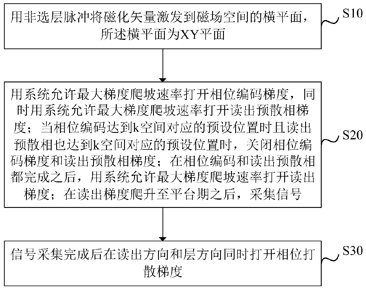
[0034] figure 1 It is a schematic diagram of a magnetic resonance projection imaging method according to an embodiment of the present invention, such as figure 1 As shown, an embodiment of the present invention provides a magnetic resonance projection imaging method, including:
[0035] Step S10, using the non-layer-selective pulse to excite the magnetization vector to the horizontal plane of the magnetic field space, and the horizontal plane is the XY plane;
[0036] Step S20, use the system to allow the maximum gradient ramp rate to open the phase encoding gradient, and at the same time use the system to allow the maximum gradient ramp rate to open the readout pre-dispersion phase gradient; when the phase encoding reaches the preset position corresponding to the k-space and read the pre-dispersion When the phase also reaches the preset position corresponding to the k-space, close the phase encoding gradient and the readout pre-dispersion gradient; after the phase encoding a...
Embodiment 2
[0060] Figure 4 It is a schematic diagram of a magnetic resonance projection imaging device according to an embodiment of the present invention, such as Figure 4 As mentioned above, the embodiment of the present invention provides a magnetic resonance projection imaging device, which is characterized in that it includes an excitation module 10, a control module 20 and a signal acquisition module 30, wherein,
[0061] The excitation module 10 is used to excite the magnetization vector to the horizontal plane of the magnetic field space with the non-layer-selective pulse, and the horizontal plane is the XY plane;
[0062] The control module 20 is used to use the system to allow the maximum gradient ramp rate to open the phase encoding gradient, and at the same time use the system to allow the maximum gradient ramp rate to open the readout pre-dispersion phase gradient; when the phase encoding reaches the preset position corresponding to the k-space and read out When the pre-d...
Embodiment 3
[0069] Figure 5 A schematic structural diagram of an electronic device for magnetic resonance projection imaging provided in an embodiment of the present invention, such as Figure 5 As shown, the device includes: a processor (processor) 801, a memory (memory) 802 and a bus 803;
[0070] Wherein, the processor 801 and the memory 802 complete mutual communication through the bus 803;
[0071] The processor 801 is used to call the program instructions in the memory 802 to execute the methods provided by the above method embodiments, for example, including: using a non-slice pulse to excite the magnetization vector to the horizontal plane of the magnetic field space, and the horizontal plane is XY flat;
[0072] Use the system to allow the maximum gradient ramp rate to open the phase encoding gradient, and at the same time use the system to allow the maximum gradient ramp rate to open the readout pre-dispersion gradient; when the phase encoding reaches the preset position corr...
PUM
 Abstract
Description
Claims
Application Information
 - R&D
- Intellectual Property
- Life Sciences
- Materials
- Tech Scout
- Unparalleled Data Quality
- Higher Quality Content
- 60% Fewer Hallucinations
Browse by: Latest US Patents, China's latest patents, Technical Efficacy Thesaurus, Application Domain, Technology Topic, Popular Technical Reports.
© 2025 PatSnap. All rights reserved.Legal|Privacy policy|Modern Slavery Act Transparency Statement|Sitemap|About US| Contact US: help@patsnap.com