Check patentability & draft patents in minutes with Patsnap Eureka AI!

Hydraulic system with clutch actuation to minimize pump losses

A technology of clutch control and hydraulic system, applied in the field of hydraulic system, can solve problems such as lack of energy efficiency

Active Publication Date: 2019-07-16
SCHAEFFLER TECH AG & CO KG
View PDF2 Cites 0 Cited by
  • Summary
  • Abstract
  • Description
  • Claims
  • Application Information

AI Technical Summary

Problems solved by technology

this is not energy efficient

Method used


Image

  • Hydraulic system with clutch actuation to minimize pump losses
  • Hydraulic system with clutch actuation to minimize pump losses

Examples


Embodiment Construction

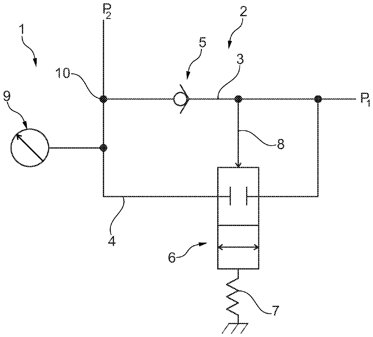
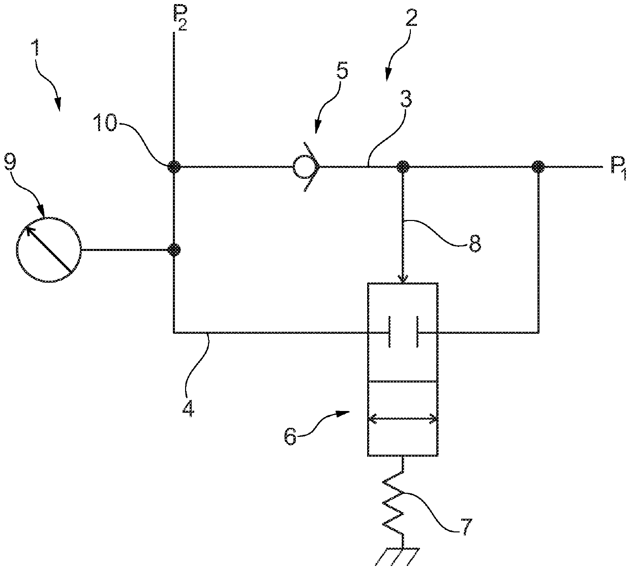
[0023] exist figure 1 A hydraulic system 1 according to the invention is shown in . A clutch actuation pressure p2 , ie the pressure that is required to actuate the clutch on the pressure chamber side, acts on the side of the hydraulic clutch actuator (not shown). The clutch itself is also not shown.

[0024] The hydraulic system 1 has a line complex 2 with a hydraulic pump (not shown) at the end, which supplies a pump pressure p1. A pressurized fluid (such as a liquid, for example oil) put under pressure by a hydraulic pump passes through the pipeline complex 2 (ie the first pipeline branch 3 and / or the second pipeline branch 4) towards the not shown clutch actuator. direction delivery. The non-return valve 5 is arranged in the first line branch 3 in such a way that it closes the passage when the pressure p1 falls below the value of p2.

[0025] In the second line branch 4 a valve 6 is used, namely a slide valve. The valve 6 is designed as a 2 / 2-way valve of the slide va...


PUM


Abstract

The invention relates to a hydraulic system (1) for supplying a hydraulic clutch actuator with pressure fluid, comprising a line coupling (2) which is connected to a hydraulic pump, wherein the line coupling (2) is prepared for conducting fluid of the pressure fluid which can be pressurised by the hydraulic pump to the clutch actuator, wherein the line coupling (2) has a first line branch (3) which has a check valve (5) and a second line branch (4) parallel to the first line branch (3), wherein a valve (6) is arranged in the second line branch (4) which can be switched back and forth according to the pressure in the first line branch (3) at least between an opening and closing position with respect to the second line branch (4). The invention further relates to a method for actuating a hydraulic clutch actuator, wherein a pump of a hydraulic system (1) is supplied with a clutch actuation pressure (p2) and a check valve (5) of a first line branch (3) is closed when a pump pressure (p1) supplied by the pump falls below the clutch actuation pressure (p2), and when the pump pressure (p1) falls further below a valve actuation pressure, a second line branch (4) parallel to the first line branch (3) is closed by the valve (6).

Description

technical field [0001] The invention relates to a hydraulic system for supplying a hydraulic clutch actuator with pressurized fluid, having a pipeline composite structure which is connected or can be connected to a hydraulic pump, wherein the pipeline composite structure is prepared For fluid guiding pressurized fluid, which can be put under pressure by the hydraulic pump, to the clutch actuator. Background technique [0002] Pressure-holding transmission clutches are known from the prior art, for example such transmission clutches with ball valves. Thus, for example DE 11 2012 004 030 T5 discloses a ball valve assembly for a clutch comprising an annular ring element comprising a first part having a first passage completely surrounded by the first part ; a first through hole, between the radially inner surface of the first part and the first passage; a second through hole, between the radially outer surface of the first part and the first passage . The ball valve assembly...

Claims


Application Information

Patent Timeline
Patent Type & Authority Patents(China)
IPC IPC(8): F16D48/02
CPCF16D48/02F16D2048/0257F16D2048/0266F16D2048/0296
Inventor T·奥萨德尼克A·帕尔门
Owner SCHAEFFLER TECH AG & CO KG
Features
  • R&D
  • Intellectual Property
  • Life Sciences
  • Materials
  • Tech Scout
  • Unparalleled Data Quality
  • Higher Quality Content
  • 60% Fewer Hallucinations
Learn More