Supercharge Your Innovation With Domain-Expert AI Agents!

Method for operating an electrically actuable feed pump in a hydraulic circuit

A technology of hydraulic circuits and delivery pumps, which is applied in the directions of transportation and packaging, registration/indicating vehicle operation, transmission control, etc., and can solve problems such as high cost, error-prone, and expensive

Active Publication Date: 2018-02-06
AUDI AG
View PDF11 Cites 0 Cited by
  • Summary
  • Abstract
  • Description
  • Claims
  • Application Information

AI Technical Summary

Problems solved by technology

However, this is not only expensive and component-intensive
Rather, level sensors can be error-prone if possible in operation

Method used


Image

  • Method for operating an electrically actuable feed pump in a hydraulic circuit
  • Method for operating an electrically actuable feed pump in a hydraulic circuit

Examples


Embodiment Construction

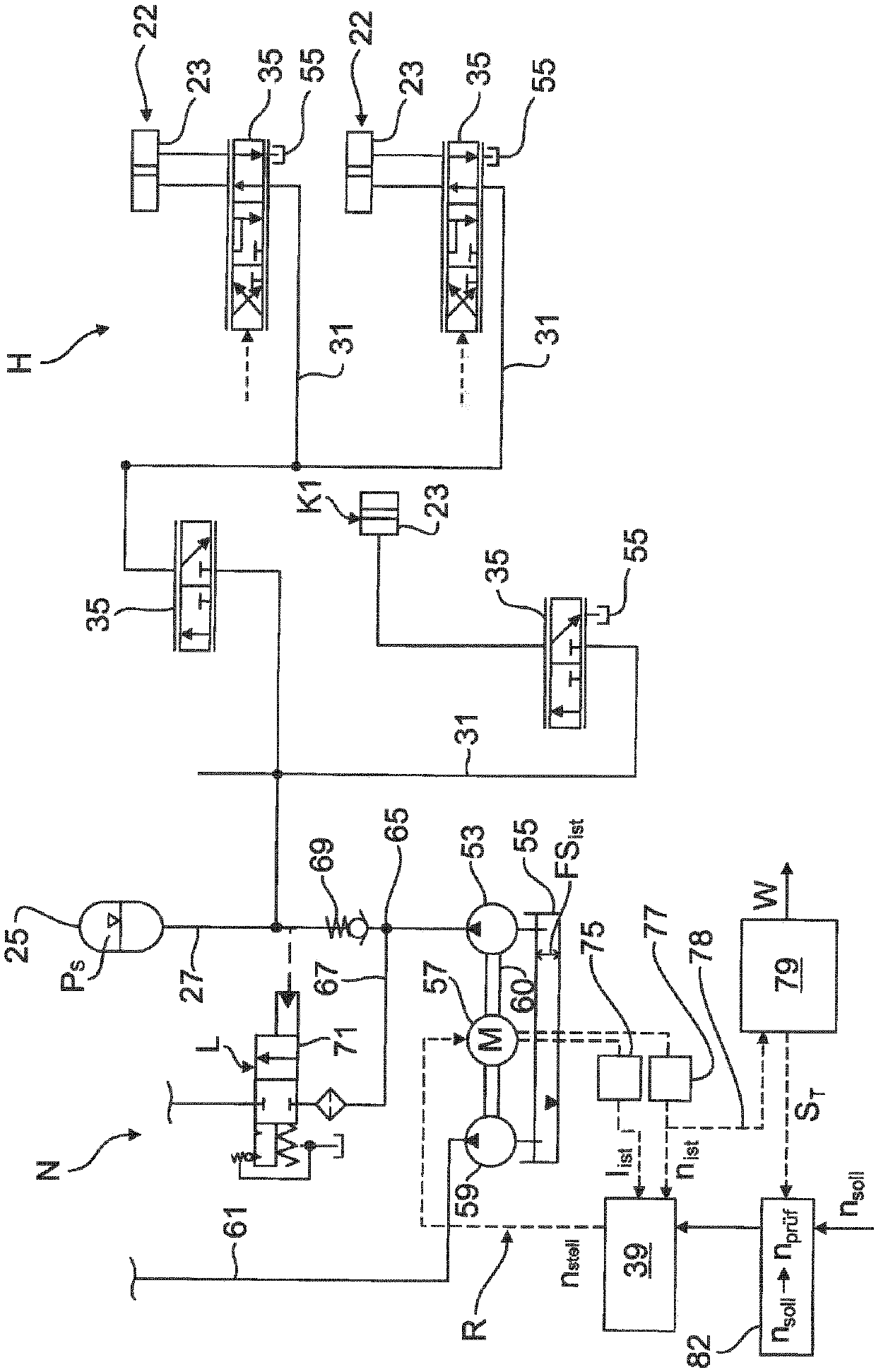
[0021] exist figure 1 The hydraulic system of a dual-clutch transmission of a motor vehicle is shown in an extremely simplified block diagram. By way of example, the hydraulic cylinder 23 of the clutch K1 and the hydraulic cylinder 23 of the actuator 22 are actuated by means of a hydraulic system. The actuator 22 is, for example, a double synchro clutch by means of which the gear changes in the dual clutch transmission take place. hydraulic system in figure 1 There is a high-voltage circuit H and a low-pressure circuit N in it. In the high-pressure circuit H, the disengagement clutch (in figure 1 Only the clutch K1) and the hydraulic cylinder 23 of the actuator 22 connected therein are shown in the figure, and the accumulator pressure p can be applied via the accumulator 25 s . For this purpose, the main line 27 , which is connected to the pressure accumulator 25 , leads to the hydraulic cylinder 23 via a sub-line 31 , not described further. A control valve 35 is arrange...


PUM


Abstract

The invention relates to a method for operating a feed pump (54, 59), which can be actuated by means of an electric motor (57), in a hydraulic circuit (N, H), which, in the case of a normal supply offluid, sucks in the fluid from a fluid sump (55) into which the fluid which is circulated in the hydraulic circuit (N, H) can be fed back, and which at least partially sucks in air the case of an undersupply of fluid, wherein the electric motor (57) is integrated into a control circuit (R) which has a control unit (39) which actuates the electric motor (57) with an actuation rotational speed (nactuate) on the basis of an actual rotational speed (nact) and a setpoint rotational speed (nsetp). According to the invention, an evaluation unit (79) for detecting the undersupply of fluid is assignedto the control unit (39). The evaluation unit (79) compares the actual rotational speed (nact) with a reference rotational speed (nmax, N), specifically in the case of respectively identical current drain (Imax). On the basis of the comparison, the evaluation unit (79) determines whether an undersupply of fluid is present.

Description

technical field [0001] The invention relates to a method according to the preamble of claim 1 for operating a delivery pump in a hydraulic circuit which is actuatable by means of an electric motor. Background technique [0002] Such a hydraulic circuit can be used, for example, in the hydraulic system of a dual-clutch transmission of a motor vehicle, in which fully automatic shifting without interruption of tractive force is possible by means of the two sub-transmissions. The transmission of the drive torque takes place via one of two clutches, which connect the two sub-transmissions with the drive. The clutch, ie the actuator for the gear, is hydraulically actuatable via the hydraulic system. For this purpose, at least one delivery pump is provided, which draws hydraulic oil from the oil tank when the hydraulic oil is normally supplied, and the hydraulic oil circulating in the hydraulic system can also flow back into the oil tank, forming a closed hydraulic circuit at the ...

Claims


Application Information

Patent Timeline
Patent Type & Authority Applications(China)
IPC IPC(8): F16H57/04F16H61/00F16H61/12
CPCF16H57/0449F16H61/0021F16H61/0031F16H61/12B60Y2400/3084F16H2061/0034F16H2061/1216F16H2061/1264G07C5/006
Inventor S·阿穆勒
Owner AUDI AG
Features
  • R&D
  • Intellectual Property
  • Life Sciences
  • Materials
  • Tech Scout
  • Unparalleled Data Quality
  • Higher Quality Content
  • 60% Fewer Hallucinations
Learn More