Vehicle body bending mode identification method under full vehicle mode

An identification method and bending mode technology, which are applied in special data processing applications, instruments, electrical digital data processing, etc., can solve the problems of high cost and complex structure of proton exchange membranes, and achieve the elimination of interference modes and high identification accuracy. , The effect of identification method is simple

Active Publication Date: 2018-02-13
CHINA AUTOMOTIVE ENG RES INST
View PDF6 Cites 0 Cited by
  • Summary
  • Abstract
  • Description
  • Claims
  • Application Information

AI Technical Summary

Problems solved by technology

[0005] The technical problem to be solved by the present invention is to provide a membraneless thermally regenerated ammonia battery an

Method used


Image

  • Vehicle body bending mode identification method under full vehicle mode
  • Vehicle body bending mode identification method under full vehicle mode

Examples


Example Embodiment

[0022] The present invention will be further specifically described below in conjunction with examples, but the implementation of the present invention is not limited thereto.

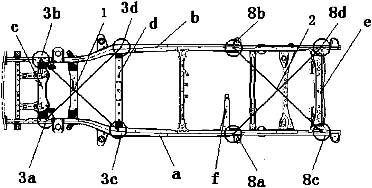
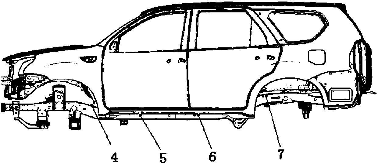
[0023] See Figure 1 to Figure 2 , The vehicle body bending mode recognition method includes the following steps:

[0024] A. Set the excitation point to identify the overall bending of the vehicle body. The excitation point includes excitation point 1 at the front end of the vehicle body and excitation point 2 at the rear end of the vehicle body. Both excitation point 1 at the front end of the vehicle body and excitation point 2 at the rear end of the vehicle body are located on the center line of the vehicle frame .

[0025] B. Set the response points to identify the overall bending of the vehicle body. The response points include the response points 3a, 3b, 3c, 3d at the front end of the vehicle body and the response points 8a, 8b, 8c, 8d at the rear end of the vehicle body, and the response points 4, Re...


PUM


Abstract

The invention discloses a vehicle body bending mode identification method under a full vehicle mode. The method is characterized by including the steps of A, setting excitation points for identifyingthe overall bending of a vehicle body, wherein the excitation points include the excitation point at the front end of the vehicle body and the excitation point at the rear end of the vehicle body which are located on the central line of the frame of the vehicle body; B, setting response points for identifying the overall bending of the vehicle body, wherein the response points include the responsepoints at the front end of the vehicle body, the longitudinal-beam response point at the lower end of a column A, the longitudinal-beam response point between the column A and a column B, the longitudinal-beam response point at the lower end of the column B, the longitudinal-beam response point at the lower end of a column C and the response points at the rear end of the vehicle body; C, applyingunit excitation load to the excitation point at the front end of the vehicle body and the excitation point at the rear end of the vehicle body, wherein the direction of the excitation load applied tothe excitation point at the front end of the vehicle body is consistent with the Y-direction coordinates of the gravity center of the front end of the frame, and the direction of the excitation loadapplied to the excitation point at the rear end of the vehicle body is consistent with the Y-direction coordinates of the gravity center of the rear end of the frame. The method is applicable to various automobile fields.

Description

technical field [0001] The invention relates to a method for identifying bending of an automobile body, in particular to a method for identifying a bending mode of an entire vehicle model body. Background technique [0002] Defining the bending mode in the NVH performance simulation process is an important task, but due to the complex structure of the whole body and the whole vehicle, in addition to the body, it also includes multiple systems such as interior decoration, exterior decoration, electrical appliances, chassis, and brakes. , and each system interacts and couples with each other, it is often difficult to define the bending mode order or to identify errors, [0003] At present, the method of obtaining the frequency response function by using the shock absorbing turret as the excitation point to evaluate the bending mode of the automobile body is often used, but this method cannot disprove the overall bending condition of the vehicle, and it is easy to cause errors....

Claims


Application Information

Patent Timeline
IPC IPC(8): G06F17/50
CPCG06F30/15G06F30/20
Inventor 苏锦涛
Owner CHINA AUTOMOTIVE ENG RES INST
Why Eureka
Try Eureka