Protection device for hot-melt pipe

A protection device and heat-melt tube technology, applied in the coupling of optical waveguide, light guide, optics, etc., can solve the problems of uneven heating, damage to the heat-melt tube, incomplete shrinkage of the heat-shrinkable tube, etc., and achieve simple structure and convenient heating , The effect of easy disassembly and assembly

Inactive Publication Date: 2018-02-23
成都兴兴蓉通信科技有限公司
0 Cites 0 Cited by

AI-Extracted Technical Summary

Problems solved by technology

[0004] The purpose of the present invention is to provide a protection device for hot-melt tubes, which solves the problems that the tradit...

Abstract

The invention discloses a protection device for a hot-melt pipe, which comprises a shell and a shell cap. There are two shell caps, which are respectively screwed to the two ends of the shell. The upper surface of the shell is provided with An air inlet, an air outlet is provided on the lower surface of the casing, a temperature sensor and a temperature display are arranged on the casing, the temperature sensor is arranged on the inside of the casing, the temperature display is arranged on the outside of the casing, and the temperature The output end of the sensor is connected to the output end of the temperature display screen. The invention is a heat-melt tube protection shell, which is wrapped in the heat-shrink tube through the protection shell, and high-temperature gas is input from the air inlet to heat the heat-shrink tube, and the heat-shrink tube passes through the shell. The temperature sensor inside the body senses the internal temperature, which is transmitted to the display screen outside the shell for display. When the display reaches 98°C, the air inlet and outlet are closed to solve the problem that the traditional direct heating method will damage the heat-melt tube and cause The problem of uneven heating and incomplete shrinkage of the heat shrinkable tube.

Application Domain

Coupling light guides

Technology Topic

Direct heatingEngineering +3

Image

  • Protection device for hot-melt pipe
  • Protection device for hot-melt pipe

Examples

  • Experimental program(1)

Example Embodiment

[0022] Example
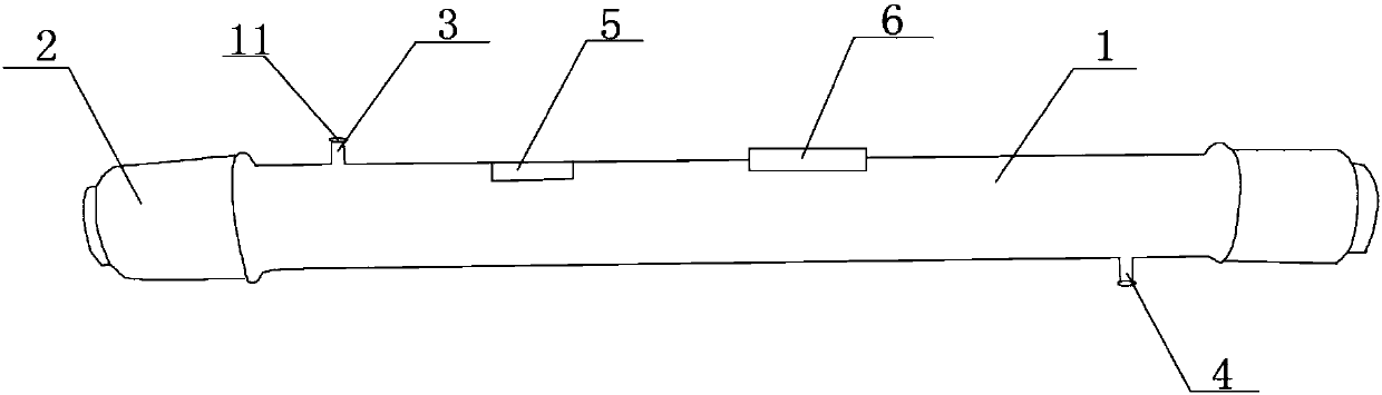
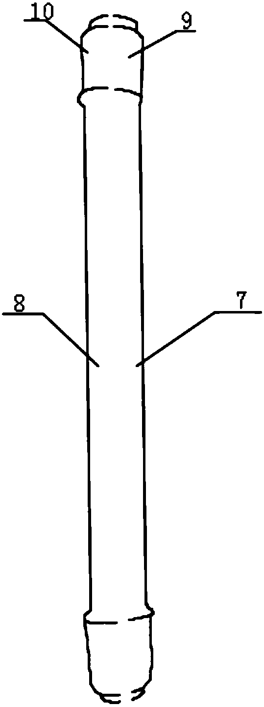
[0023] Such as figure 1 , 2 As shown, a protection device for a hot melt tube of the present invention includes a shell 1 and a shell cap 2. The number of shell caps 2 is two, which are respectively connected to both ends of the shell 1 by threads, and belong to the shell cap 2. Both ends of the housing 1 are provided with openings, the upper surface of the housing 1 is provided with an air inlet 3, the lower surface of the housing 1 is provided with an air outlet 4, and the housing 1 is provided with a temperature sensor 5 and a temperature display The temperature sensor 5 is arranged on the inside of the housing 1, the temperature display 6 is arranged on the outside of the housing 1, and the output terminal of the temperature sensor 5 is connected to the output terminal of the temperature display 6. The housing 1 also includes The upper half shell 7 and the lower half shell 8 are connected by screws between the upper half shell 7 and the lower half shell 8. The shell cap 2 includes an upper half shell cap 9 and a lower half shell cap 10, so The upper half shell cap 9 and the lower half shell cap 10 are connected by screws. The shell 1 includes an insulation layer and a waterproof layer. The waterproof layer is arranged on the outside of the shell 1, and the insulation layer is arranged on the inside of the shell. Both the air inlet 3 and the air outlet 4 are provided with a plug 11, and the diameter of the plug 11 is equal to the diameter of the air inlet 3 and the air outlet 4.
[0024] This shell fixes the shell 1 and the shell cap 2 outside the hot melt pipe through screw connection, and fixes the shell cap 2 on the shell 1 through the screw connection. The high temperature gas is input from the air inlet 3, and the air outlet 4 is opened to discharge the previous The air heats the heat shrinkable tube, and the temperature sensor inside the housing 1 senses the internal temperature, which is transmitted to the display on the outside of the housing 1 for display. When it displays 98°C, plug the air inlet 3 with a plug 13 And the air outlet 4, heat the hot melt tube, so as to solve the problem that the traditional direct heating method will damage the hot melt tube, and will cause uneven heating and incomplete shrinkage of the heat shrink tube.

PUM

no PUM

Description & Claims & Application Information

We can also present the details of the Description, Claims and Application information to help users get a comprehensive understanding of the technical details of the patent, such as background art, summary of invention, brief description of drawings, description of embodiments, and other original content. On the other hand, users can also determine the specific scope of protection of the technology through the list of claims; as well as understand the changes in the life cycle of the technology with the presentation of the patent timeline. Login to view more.

Similar technology patents

Photoelectric sensor for position of sun

InactiveCN101650173AEffective tracking range expandedSimple structure
Owner:WUHAN UNIV OF TECH

Magnetic cooling apparatus and control method thereof

ActiveUS20130180263A1simple structure
Owner:SAMSUNG ELECTRONICS CO LTD

Dual-Drivetrain of Power-Assist Vehicle

InactiveUS20100181130A1enhance uphill momentumsimple structure
Owner:CHOU WEN CHENG

Classification and recommendation of technical efficacy words

Why Eureka
Try Eureka