Check patentability & draft patents in minutes with Patsnap Eureka AI!

optical relay device

A relay device, light source technology, applied in electromagnetic repeaters, electromagnetic transceivers, electrical components and other directions, can solve problems such as limiting transmission distance

Inactive Publication Date: 2018-09-25
MITSUBISHI ELECTRIC CORP
View PDF6 Cites 0 Cited by
  • Summary
  • Abstract
  • Description
  • Claims
  • Application Information

AI Technical Summary

Problems solved by technology

[0007] In addition, when the transmission capacity of the optical transmission system is expanded by changing the used modulation method to a method with a larger modulation multi-ary number, the multi-ary system of the modulation method is accompanied by the multi-ary system of the modulation method. However, the problem of limiting the transmission distance

Method used


Image

  • optical relay device
  • optical relay device
  • optical relay device

Examples


Embodiment approach

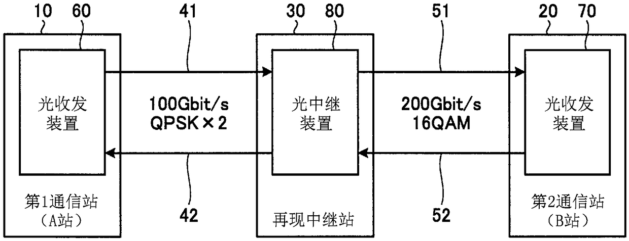
[0032] figure 1 It is a diagram showing a configuration example of an optical transmission system to which the optical relay device of the present embodiment is applied. The optical transmission system is configured to include: a first communication station 10, which transmits and receives a 100 Gbit / s optical signal; a second communication station 20, which transmits and receives a 200 Gbit / s optical signal; and a reproduction relay station 30, which transmits and receives an optical signal from the first The optical signal transmitted from the first communication station 10 is reproduced and relayed to the second communication station 20 , and the optical signal transmitted from the second communication station 20 is reproduced and relayed to the first communication station 10 .

[0033] The first communication station 10 has an optical transceiver 60 , and the second communication station 20 has an optical transceiver 70 . The reproduction relay station 30 has an optical r...


PUM


Abstract

Optical relay apparatus of the present invention (80) having: the 1st signal conversion portion (81), which converts the received optical signal into an electrical signal and demodulates and outputs, modulates the input electrical signal in the 1st modulation mode and converts it into an optical signal and transmits it; And the second signal conversion portion (82), which modulates the electrical signal output from the 1st signal conversion section (81) in a second modulation manner and converts it to an optical signal and transmits it, converts the received optical signal into an electrical signal and demodulates it as an input to the electrical signal output of the first signal conversion section (81).

Description

technical field [0001] The invention relates to an optical relay device, an optical transmission system and an optical signal reproduction and relay method for reproducing and relaying optical signals. Background technique [0002] In order to be able to use optical fiber for long-distance and large-capacity transmission, it is necessary to achieve high-density signal multiplexing, overcome the degradation of signal-to-noise power ratio caused by optical amplification, and overcome the waveform distortion caused by fiber nonlinear optical effects. [0003] As a technique for realizing large-capacity transmission, there is a method of increasing the transmission capacity per optical fiber by changing the used modulation scheme to a modulation scheme with a large number of modulation aryls. In addition, there is a method of increasing transmission capacity by loading different information on a plurality of optical carriers or optical subcarriers and performing high-density wav...

Claims


Application Information

Patent Timeline
Patent Type & Authority Patents(China)
IPC IPC(8): H04B10/29
CPCH04B10/29H04B10/40H04B10/5161H04B10/541H04B10/5561H04B10/612H04B10/613H04B10/614H04B10/616H04J14/06
Inventor 吉田刚
Owner MITSUBISHI ELECTRIC CORP
Features
  • R&D
  • Intellectual Property
  • Life Sciences
  • Materials
  • Tech Scout
  • Unparalleled Data Quality
  • Higher Quality Content
  • 60% Fewer Hallucinations
Learn More