Tree support device
A tree support and tree technology, which is applied in the field of tree support devices, can solve the problems of reducing clamping force, decreasing windproof performance, affecting root consolidation, etc., to achieve the effect of reducing damage and ensuring healthy growth
- Summary
- Abstract
- Description
- Claims
- Application Information
AI Technical Summary
Problems solved by technology
Method used
Image

Examples
Embodiment 1
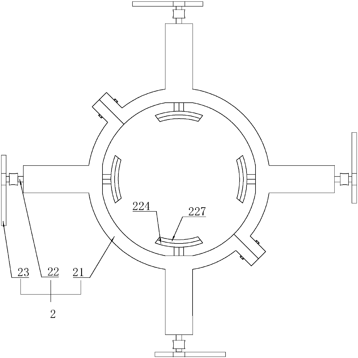
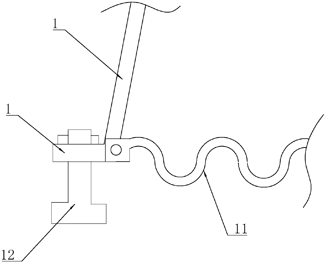
[0040] Embodiment 1: a kind of tree supporting device, such as figure 1 with 3 As shown, it includes a tripod 1 fixed on the ground, a straightening mechanism 2 fixed on the tripod 1 and a reset mechanism 3 for resetting the straightening mechanism 2 .
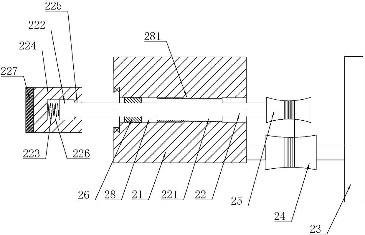
[0041] refer to figure 1 with figure 2 , the righting mechanism 2 includes a base frame 21, four push rods 22 and four first wind wheels 23 evenly distributed on the base frame 21 along the circumferential direction, the push rods 22 correspond to the first wind wheels 23 one-to-one, and the push rods The end of 22 faces the center of base frame 21 . Wherein, the base frame 21 surrounds the tree and is fixedly connected with the tripod 1 , and the base frame 21 is divided into two parts along the radial direction and fixed by bolts. The base frame 21 is provided with a through hole 28 for the push rod 22 to pass through. The second threaded portion 281 and the retaining ring 26 threadedly connected with the through hole 2...
Embodiment 2
[0049] Embodiment 2: as Figure 4 with Figure 5 As shown, the difference from Embodiment 1 lies in that the structure and mode of action of the reset mechanism 3 are different.
[0050] The reset mechanism 3 includes a ratchet 27 rotatably connected to the base frame 21 and a detachable pawl 34 connected to the base frame 21, wherein the push rod 22 slides through the center of the ratchet 27 and is connected to the ratchet 27 in a non-rotational manner; 27 and the base frame 21 are provided with a return torsion spring.
[0051] The base frame 21 is provided with a mounting hole 345; the ratchet 34 includes a claw head 341 partially slipped through the mounting hole 345, a suspension rod 342 threaded through the base frame 21, and a mechanism for forcing the claw head 341 to break away from the mounting hole 345. Reset spring 343; where the claw head 341 is provided with a sliding cavity 344, the end of the suspension rod 342 slides through the sliding cavity 344 and the e...
Embodiment 3
[0054] Embodiment 3: as Figure 6-8 As shown, the difference from Embodiment 2 lies in that the reset structure and mode of action are different, and the structure of the second wind wheel 31 is added on the basis of Embodiment 2.
[0055] The end of the push rod 22 away from the ratchet wheel 27 is fixed with a second driven wheel 33, the second wind wheel 31 is arranged on the base frame 21, and one side of the axial direction of the second wind wheel 31 is fixed with a second driven wheel 31 linked with the second wind wheel 31. The second winding wheel 32 ; the second driven wheel 33 is linked with the second winding wheel 32 in a winding manner and drives the suspension rod 342 to move toward the ratchet wheel 27 ; the suspension rod 342 is provided with a second torsion spring between the base frames 21 .
[0056] Way of working:
[0057] When driven by the wind, the movement mode of the push rod 22 and the ratchet 27 is the same as in the second embodiment. At the same...
PUM
 Abstract
Description
Claims
Application Information
 - Generate Ideas
- Intellectual Property
- Life Sciences
- Materials
- Tech Scout
- Unparalleled Data Quality
- Higher Quality Content
- 60% Fewer Hallucinations
Browse by: Latest US Patents, China's latest patents, Technical Efficacy Thesaurus, Application Domain, Technology Topic, Popular Technical Reports.
© 2025 PatSnap. All rights reserved.Legal|Privacy policy|Modern Slavery Act Transparency Statement|Sitemap|About US| Contact US: help@patsnap.com