
Deceleration device combining with motor

A deceleration device and motor technology, applied in the direction of electromechanical devices, transmission parts, control of mechanical energy, etc., can solve the problem of the best combination of tooth number differences, such as unclear teaching

Active Publication Date: 2018-03-06
SAFEWAY ELECTRO MECHANICAL CO LTD +1
View PDF9 Cites 1 Cited by
  • Summary
  • Abstract
  • Description
  • Claims
  • Application Information

AI Technical Summary

Problems solved by technology

Others, such as the difference in the number of teeth between the stationary ring gear and the driving ringgear, and the optimal combination of the number of planetary gears are not clearly taught, and even the influence of the number of planetary gears on the reduction ratio is ignored. These need to be improved and clarified

Method used


Image

  • Deceleration device combining with motor
  • Deceleration device combining with motor
  • Deceleration device combining with motor

Examples


Embodiment Construction

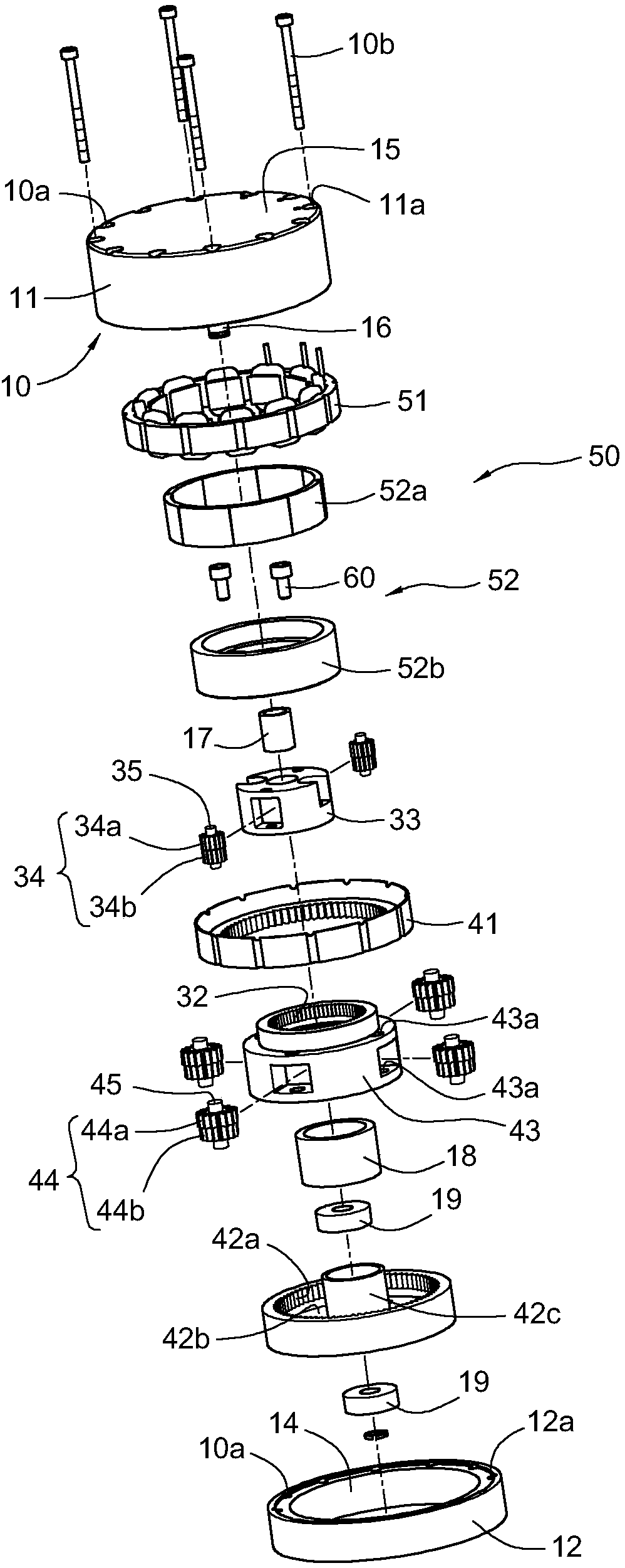
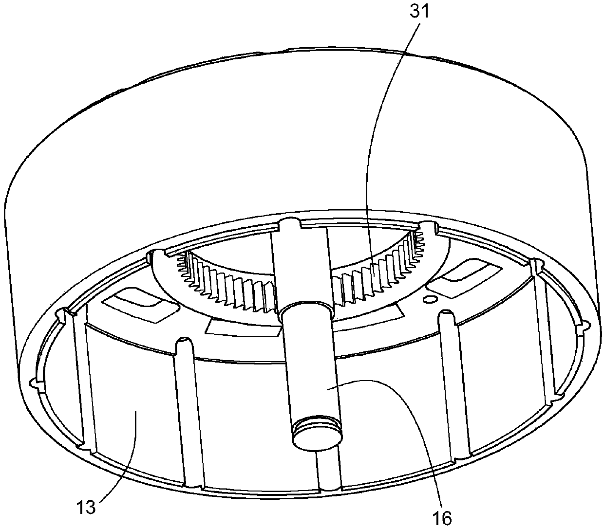
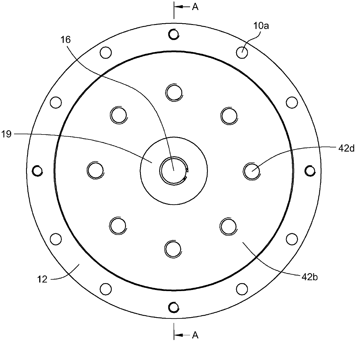
[0033] First, please merge the Figure 1 to Figure 6 , disclose the configuration details of a preferred embodiment of the present invention, and describe the reduction gear unit provided by the present invention combined with the motor, or called the motor reduction gear unit, and its structural composition includes a casing 10, a support shaft 16, a reducer 20 and a hollow motor 50 .

[0034] Depend on figure 1 and Figure 4 It can be seen that the casing 10 includes a first casing 11 and a second casing 12 . A plurality of through holes 11a are formed on the peripheral edge of the first casing 11, and a corresponding number of screw holes 12a are formed on the peripheral edge of the second casing 12. The first casing 11 is connected to the first casing 11 with a corresponding number of screws 10b. The second casing 12 is assembled with screws to form a casing 10 . A closed end surface 15 and an open hole 14 are respectively formed at both ends of the casing 10 ; wherein...


PUM


Abstract

The invention provides a deceleration device combining with a motor, and the device comprises a speed reducer and a hollow motor which are configured in a motor case with a central supporting shaft. The hollow motor is arranged around the periphery of a first-order planetary gear system, and the speed reducer comprises a multi-order planetary gear system. The planetary gear system at each order comprises one fixed inner gear ring, one movable inner gear ring, one planetary gear group and one bearing seat. The bearing seats and the movable inner gear rings of the planetary gear system at the adjacent orders are enabled to have the characteristic of integrated fixed connection for power transmission, thereby achieving the extended outputting of motor power to the outside of the motor case soas to solves a problem that a conventional motor speed reducer just can output a limited speed reduction ratio and a problem that the overall configuration space (volume) is difficult to reduce.

Description

technical field [0001] The invention relates to a combined technology of a motor and a gear reduction mechanism, in particular to a motor reduction device provided with a fixed end to provide a fixed support shaft pivotally connected to a multi-stage planetary gear train without sun gears. Background technique [0002] A motorized speed reducer, or a geared motor, is an integrated power drive device that combines an electric motor and a gear reduction mechanism, or a non-gear reducer. Generally, under the same driving voltage, if the motor has low speed and high torque output, the volume is usually relatively large, and the production cost is also high. If the motor has high speed and low torque output, the volume is usually relatively small, and the production cost is also high. Low speed, while the motor reducer allows the motor to be converted into low speed and high torque through the reducer under the condition of generating high speed and low torque, providing huge tor...

Claims


Application Information

Patent Timeline
IPC IPC(8): H02K7/116F16H57/023F16H57/08
CPCF16H57/023F16H57/08F16H2057/02086H02K7/116
Inventor 梁嘉生
Owner SAFEWAY ELECTRO MECHANICAL CO LTD
Learn More