[0021] The present invention will be described in detail below in conjunction with the drawings.
[0022] In order to make the objectives, technical solutions, and advantages of the present invention clearer, the following further describes the present invention in detail with reference to the accompanying drawings and embodiments. It should be understood that the specific embodiments described herein are only used to explain the present invention, but not to limit the present invention.
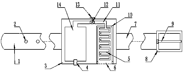
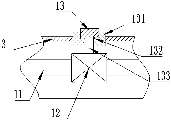
[0023] Such as Figure 1-Figure 5 As shown, the present invention discloses an intelligent safety diving device control system, which includes an airbag release device and a fixing device. The airbag release device includes a housing 3 in which a gas storage tank 14 is provided, and the gas storage tank 14 passes through a connecting pipe 11. The airbag 5 is connected, the airbag 5 is arranged in the housing 3, the connecting pipe 11 is provided with a valve 12, the valve 12 is opened, the air in the air tank 14 can enter the airbag 5; it also includes an intelligent safety device, which is arranged in Inside the housing 3; the intelligent safety device includes a main control unit 24, a heart rate sensor 20, the heart rate sensor 20 is connected to the main control unit 24 by a cable signal, the intelligent safety device includes a charging coil 25, the charging coil 25 is electrically connected to the main control unit 24 through a conditioning circuit Connection; also includes a charging device, the charging device includes a charging base 31, the charging base 31 is provided with a transmitter coil 32.
[0024] Further, the present invention discloses a preferred structure of an intelligent safety diving device control system, including an airbag cover 10, the airbag 5 is arranged in the airbag cover 10, the airbag cover 10 is in the housing 3, and one end of the airbag cover 10 is provided with an outlet A through hole is opened on the housing where the outlet of the airbag cover 10 is connected to the housing 3; the housing 3 is provided with a guide channel 131, the guide channel 131 is opened with a stepped through hole, and a transmission rod 133 is provided in the guide channel 131 The small-diameter part of the transmission rod 133 and the stepped hole of the guide channel 131 passes through the guide channel 131 and is connected to the valve 12 in power. A button 13 is provided in the guide channel 131 at the top of the transmission rod 133, and a step hole of the button 13 and the guide channel 131 The large-diameter part is movably connected with the button 13 and the guide channel 131 is provided with a waterproof lubricating material; the step in the step through hole is provided with a return spring 132 between the button 13 and the valve 12 can be synchronized when the button 13 is pressed Opening and closing.
[0025] Further, the intelligent safety device includes a water temperature sensor 15 and a water pressure sensor 16. The water temperature sensor 15 and the water pressure sensor 16 are signally connected to the main control unit 24 through a cable; the housing 3 is provided with a water temperature sensor 15 and a water pressure sensor 16 The water temperature sensor 15 and the water pressure sensor 16 are connected to the outside through the through holes; the conditioning circuit includes a filter 26 and a rectifier 27. The output end of the charging coil 25 is electrically connected to the input end of the rectifier 27 through a cable. The output end of the filter 26 is electrically connected to the input end of the filter 26 through a cable, and the output end of the filter 26 is electrically connected to the main control unit 24.
[0026] Further, the gas storage tank 14 is provided with an inflation port 4, and an inflation channel is opened on the wall of the housing 3 opposed to the inflation port 4; the intelligent safety device includes a body temperature sensor 19, a blood oxygen sensor 21, a body temperature sensor 19, The blood oxygen sensor 21 is signally connected to the main control unit 24 through a cable; the sensing parts of the body temperature sensor 19, the heart rate sensor 20, and the blood oxygen sensor 21 are arranged at the bottom of the housing 3; the intelligent safety device also includes a hydrophone 22, vibration The charging device 23, the hydrophone 22, and the vibrator 23 are electrically connected to the main control unit 24 through a cable; the charging device includes a base 28, the top of the base 28 is provided with a bracket 30, the top of the bracket 30 extends horizontally with a connecting rod, and the top of the connecting rod is connected to The side of the charging stand 31 is connected, and the side of the base 28 is provided with a plurality of balance frames 29 for keeping the balance of the charging device.
[0027] Further, a first wristband 1 is movably connected to the shell 3, and a plurality of fixing holes 2 are evenly opened on the first wristband 1; the shell 3 is movably connected to the second wristband 1 on the opposite side. Wrist strap 7, the end of the second wrist strap 7 is movably connected with a loop buckle 8, and the middle of the loop buckle 8 is movably linked with a fixed pin 9; when the first wrist strap 1 passes through the loop buckle 8, the fixed pin 9 can be inserted into the fixing hole 2 The ring formed by the first wristband 1 and the second wristband 7 is fixed.
[0028] Further, the airbag 5 is provided with an exhaust port, which can be opened and closed freely; the air pressure of the air storage tank 14 is 0.8-3.2MPa; the smart safety device includes a battery 18, and the housing 3 is provided with Switch 17, the battery 18 is electrically connected to the main control unit 24 through the switch 17; the charging device also includes a charging circuit, the charging circuit includes a step-down transformer, a rectifier circuit, a filter circuit, an oscillating circuit, the input end of the step-down transformer and the mains The power supply is connected, the output terminal of the step-down transformer is electrically connected with the input terminal of the rectifier circuit, the output terminal of the rectifier circuit is electrically connected with the input terminal of the filter circuit, the output terminal of the filter circuit is electrically connected with the input terminal of the oscillating circuit, and the output of the oscillating circuit The terminal is electrically connected to the transmitting coil 32.
[0029] For specific use, fix the device on a person's wrist or foot, and you can enjoy free diving.
[0030] In the specific operation process, when you encounter danger or need to float up during swimming, manually press the button 13 and the button 13 pushes the valve 12 to open. The high-pressure air in the air storage tank 14 enters the airbag 5 through the connecting pipe 11, and the airbag 5 is inflated Inflation, the airbag 5 is ejected from the airbag cover 10 and gradually expands in the water, increasing the buoyancy, bringing people to the surface of the water, and protecting people's safety.
[0031] After use, the airbag 5 is exhausted through the exhaust port, and then the airbag 5 is folded and put into the airbag cover 10 again, and the air tank 14 is inflated from the inflation port 4 through the inflator, so that the equipment It can be reused to improve the utilization of equipment. The diving depth is limited to ensure the reliability of the safety equipment. When diving, the water pressure produces a certain thrust on the button 13. When the diving depth is too deep, the button 13 pushes the transmission rod under the action of water pressure. 133 opens the valve 12 and the airbag 5 is inflated, driving the human body to float.
[0032] When diving, press switch 17 to activate the smart safety device. The water temperature sensor 15 and the water pressure sensor 16 convert the state of the water body into electrical signals and transmit them to the main control unit 24. The body temperature sensor 19, heart rate sensor 20, and blood oxygen sensor 21 convert various physical parameters of the human body into digital signals and transmit them to The main control unit 24, based on the received information, transmits relevant information to people by controlling the hydrophone 22 and the vibrator 23. Protect the safety of divers.
[0033] In this way, by setting up this device, it can provide people with a kind of safety protection during swimming or diving, and protect people's life safety; this device can be used repeatedly and can be used as an auxiliary floating device for diving contact to improve diving pleasure; Reduce the investment cost of diving safety devices and reduce the entry conditions for diving.
[0034] When charging, the safety device is placed on the charging base 31, and the charging base 31 is connected to the power source. This can be charged.
[0035] During the charging process, the step-down transformer reduces the voltage of the mains power to a suitable value and transmits it to the rectifier circuit. The rectifier circuit converts the alternating current into a high-low-variable direct current. The electrical energy continues to be transmitted to the filter circuit. After the filter circuit receives the alternating current in the direct current The components are filtered out and become a steady direct current. The output terminal of the filter circuit is also provided with a voltage stabilizing circuit to further maintain the stability of the voltage. Then the direct current is transferred to the oscillating circuit, and the oscillating circuit converts the direct current into high-frequency alternating current and transmits it through the transmitting coil 32. The transmitting coil 32 converts the alternating current into an alternating magnetic field.
[0036] An alternating magnetic field is passed into the charging coil 25, and an alternating current is generated in the charging coil 25, which is then input to the rectifier 27. The rectifier 27 converts the alternating current into a direct current and passes it to the filter 26. The filter 26 filters out the alternating current. It is input to the main control unit 24, and the main control unit 24 transmits the electric energy to the battery 18 for storage after receiving it, thus realizing the charging function.
[0037] The above are only the preferred embodiments of the present invention and are not intended to limit the present invention. Any modification, equivalent replacement and improvement made within the spirit and principle of the present invention shall be included in the protection of the present invention. Within range.