
Rotary wing aircraft carrier system capable of being quickly disassembled and installed

A technology for rotating wings and aircraft, which is applied to aircraft parts, aircraft control, and air flow affecting the surface of the aircraft. problem, to achieve the effect of reducing the lateral size, facilitating concealed deployment, and modular design

Active Publication Date: 2018-03-16
NORTHWESTERN POLYTECHNICAL UNIV
View PDF7 Cites 3 Cited by
  • Summary
  • Abstract
  • Description
  • Claims
  • Application Information

AI Technical Summary

Problems solved by technology

[0005] Due to the large lateral size of the wings of traditional fixed-wing UAVs, when they are transported by road or railway, they will exceed the width limit requirements of the specific mode of transport, resulting in the need for coordination in various aspects during the transport process, making it difficult to meet the needs of rapid and timely delivery. requirements; moreover, the space utilization rate of this method is also very low, and the UAV is also exposed during the transportation process, and can only be camouflaged and concealed by covering and other methods
In addition, there are current

Method used


Image

  • Rotary wing aircraft carrier system capable of being quickly disassembled and installed
  • Rotary wing aircraft carrier system capable of being quickly disassembled and installed
  • Rotary wing aircraft carrier system capable of being quickly disassembled and installed

Examples


Example Embodiment

[0024] The embodiments of the present invention will be described in detail below. Examples of the embodiments are shown in the accompanying drawings, wherein the same or similar reference numerals indicate the same or similar elements or elements with the same or similar functions. The embodiments described below with reference to the accompanying drawings are exemplary, and are intended to explain the present invention, but should not be construed as limiting the present invention.

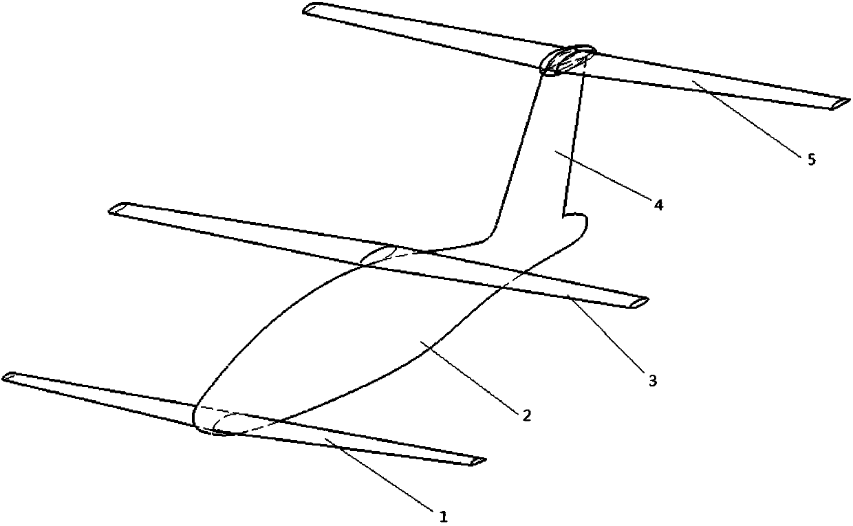
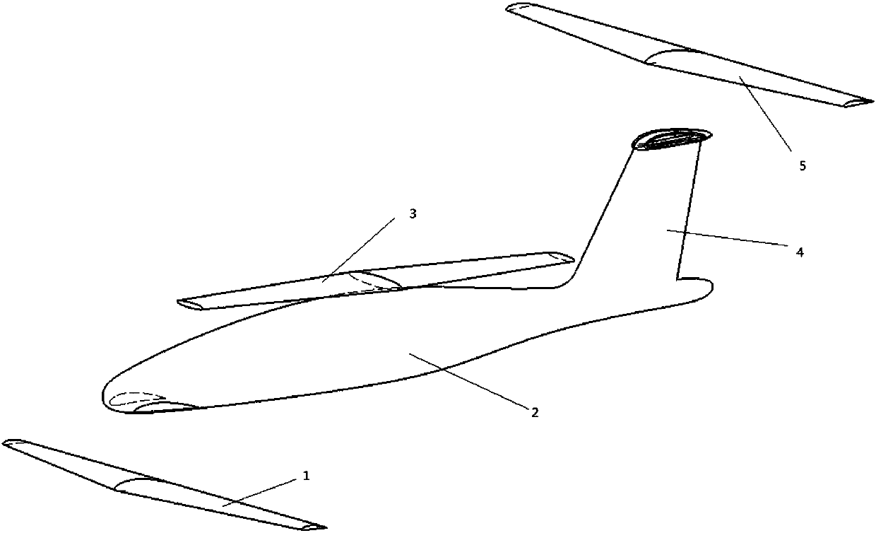
[0025] Rotating Wing Aircraft (CRW) is a new concept unmanned aerial vehicle with three-wing layout that the patent applicant has focused on in the past many years. It has both the vertical take-off and landing performance of a helicopter and the high cruise performance of a fixed-wing aircraft. In order to have the advantages of both helicopters and fixed-wing aircraft, the aircraft is designed to have two flight modes, namely rotor mode and fixed-wing mode. In the take-off and landing phase, the ...


PUM


Abstract

The invention provides a rotary wing aircraft carrier system capable of being quickly disassembled and installed. The rotary wing aircraft carrier system includes a loading box, splints, and a rotarywing aircraft; the rotary wing aircraft includes a duck wing which can be disassembled independently, a fuselage, a rotatable main wing, a vertical tail, and a horizontal tail which can be disassembled independently; when the rotary wing aircraft is in the transport and storage state, the rotatable main wing is locked in the longitudinal direction of the fuselage, the duck wing and the horizontaltail are disassembled and stacked at the upper part of the rotatable main wing in the longitudinal direction of the fuselage; the splints are divided into a front splint and a rear splint; four through grooves are formed in the splints, and the shapes of the four through grooves are matched with the shapes of the cross sections of the duck wing, the horizontal tail, the rotatable main wing, and the fuselage at the installation position of the splints respectively; when the rotary wing aircraft is in the transport and storage state, the front splint and the rear splint respectively fix the duckwing, the horizontal tail, and the rotatable main wing in the longitudinal direction of the fuselage at the front part and the rear part of the aircraft. By adopting the rotary wing aircraft carriersystem, the lateral size of the rotary wing aircraft during transport and storage can be greatly reduced to facilitate the fast concealed deployment of the rotary wing aircraft.

Description

Technical field [0001] The invention relates to the field of transport design of medium and large unmanned aircraft, in particular to a rotary wing aircraft transport system that can be quickly disassembled and installed. Background technique [0002] Rotary-wing aircraft is a new concept unmanned aerial vehicle with three-wing layout, which combines the vertical take-off and landing performance of a helicopter and the high cruise performance of a fixed-wing aircraft. In order to have the advantages of both helicopters and fixed-wing aircraft, the aircraft is designed to have two flight modes, namely rotor mode and fixed-wing mode. In the take-off and landing phase, the rotor flight mode is adopted, the wing rotates at high speed and periodically swings; in the cruise and mission phase, the rotor is decelerated and fixed at a designated position, and the swing motion is locked during the deceleration of the rotor. Fixed-wing flight mode. [0003] Rotary wing aircraft has the char...

Claims


Application Information

Patent Timeline
IPC IPC(8): B64F5/50B64C1/30
CPCB64C1/30B64F5/50
Inventor 高正红田力邓阳平闫晓坤那洋高楠
Owner NORTHWESTERN POLYTECHNICAL UNIV
Features
  • Generate Ideas
  • Intellectual Property
  • Life Sciences
  • Materials
  • Tech Scout
  • Unparalleled Data Quality
  • Higher Quality Content
  • 60% Fewer Hallucinations
Learn More