Welding mechanism of vacuum welding furnace

A vacuum welding furnace and welding mechanism technology, applied in welding equipment, manufacturing tools, metal processing, etc., can solve the problems of slow cooling speed, sheet deformation, low welding efficiency, etc., achieve rapid heating and cooling, and reduce energy consumption , The effect of improving the welding speed

Pending Publication Date: 2018-03-27
SHANDONG CAIJU ELECTRONICS TECH CO LTD
View PDF12 Cites 5 Cited by
  • Summary
  • Abstract
  • Description
  • Claims
  • Application Information

AI Technical Summary

Problems solved by technology

[0004] (1) There is only one heating zone that matches the vacuum processing device on the machine table. Since the material needs to be heated to a certain temperature to melt the solder paste and achieve the welding effect, the heating of the material requires time to move , resulting in a long heating time, and because the heating zone is set on the upper cover, the heating zone uses radiation to heat the material, and the heat transfer efficiency is low, which further increases the heating time of the material, making its welding efficiency low ;
[0005] (2) The temperature of the blanks after welding is to

Method used


Image

  • Welding mechanism of vacuum welding furnace
  • Welding mechanism of vacuum welding furnace
  • Welding mechanism of vacuum welding furnace

Examples


Example Embodiment

[0056] Example 1

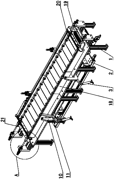
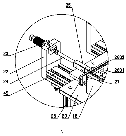
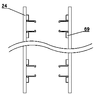
[0057] Such as Figure 1~2 As shown: the lower side of the welding chamber 18 is provided with a transport mechanism 2, and the welding chamber 18 is provided on the upper side of the frame 1. The conveying mechanism 2 includes a conveying rod 24 and a lifting mechanism, a translation mechanism, and an opening and closing mechanism arranged on the lower side of the welding chamber 18. The middle of the conveying rod 24 is arranged in the welding chamber 18, and both ends of the welding chamber 18 are closed by end covers 26, And each end cover 26 is provided with a carrying port 2601 on both sides, the carrying rod 24 is arranged horizontally along the length of the welding chamber 18, and two carrying rods 24 are symmetrically arranged on both sides of the welding chamber 18, and each carrying rod 24 Both ends pass through the port 2601 of the end cap 26 and extend. The lower side of the welding chamber 18 is horizontally provided with a carrying and mounting...

Example Embodiment

[0089] Example 2

[0090] The difference between embodiment 2 and embodiment 1 is that the supporting part is directly mounted on the transport rod 24, the heating plate 30 is provided with heating plate relief openings 3001 at both ends, and the cooling plate 28 is provided with cooling plate relief openings at both ends 2801, the supporting part supports the material piece through the two ends of the material piece.


PUM


Abstract

The invention provides a welding mechanism of a vacuum welding furnace, belonging to the technical field of vacuum welding. The mechanism is characterized by comprising a welding chamber (18), and a furnace cover which is arranged at the upper side of the welding chamber (18), wherein a welding cavity is arranged between the furnace cover (4) and the welding chamber (18); a welding platform (20) is arranged at the lower part of the welding chamber (18); a heating area is arranged at one side, close to the feeding end, of the welding platform (20); a cooling area is arranged at one side, closeto the discharging end, of the welding platform (20); a negative pressure pumping module (9) is arranged at the upper side of one end, close to the cooling area, of the heating area; the negative pressure pumping module (9) is mounted on the furnace cover (4) by lifting, and the bottom part of the negative pressure pumping module (9) encircles a closed negative pressure chamber with the heating area; a protecting gas inlet pipe is arranged on the welding chamber (18) or the furnace cover (4). With the adoption of the mechanism, sheets can be quickly welded in the negative pressure cavity and are prevented from reacting with oxygen during heating.

Description

technical field [0001] A welding mechanism of a vacuum welding furnace belongs to the technical field of vacuum welding. Background technique [0002] During the production of electronic components such as diodes, triodes, thyristors or bridges, chips need to be welded between the upper material and the lower material. This process is called bonding. The specific working process of the assembling is as follows: First, it is necessary to apply solder paste on the upper side of the lower material, and place the chip on the specific position of the lower material, and then stack the upper material with the solder paste on the lower side on the lower material. On the upper side of the sheet, cover the top cover of the welding mold on the bottom plate of the welding mold, and finally send the welding mold into the welding furnace for welding. The welding of blanks needs to be carried out in a vacuum furnace. [0003] The Chinese utility model patent with application number 2014...

Claims


Application Information

Patent Timeline
IPC IPC(8): B23K3/00B23K3/08B23K1/008
CPCB23K1/008B23K3/00B23K3/08
Inventor 李向东
Owner SHANDONG CAIJU ELECTRONICS TECH CO LTD
Why Eureka
Try Eureka