Supercharge Your Innovation With Domain-Expert AI Agents!

Length-adjustable integral stern shaft tube device

A stern tube and integral technology, which is applied in the field of integral stern tube devices, can solve problems such as increased cost, high labor intensity, and limited construction conditions, and achieves improved accuracy and reliability, reduced labor intensity, and compensates for installation deviations Effect

Pending Publication Date: 2018-03-27
CSSC HUANGPU WENCHONG SHIPBUILDING COMPANY
View PDF0 Cites 3 Cited by
  • Summary
  • Abstract
  • Description
  • Claims
  • Application Information

AI Technical Summary

Problems solved by technology

[0003] In the past, the stern tube device was carried out in the berth and dock for high-precision operations such as boring and press-fitting bearings. Due to the complex construction environment and limited construction conditions in the shipyard, it is often difficult to meet the requirements for the above-mentioned operations at one time, which is not only labor-intensive. Large size, low work efficiency, long cycle time, and great risk of failure. Even if the stern tube is successfully installed in the end, its safety and reliability will be greatly compromised
Secondly, since the segmented structure of the hull will produce large errors when closing, and these errors are unpredictable, therefore, when the stern tube device is installed, there will often be a front-to-back position deviation, and the construction personnel can only place the stern tube. Rework or replacement of some components of the shaft tube device can make up for the deviation, which not only increases the amount of extra labor, but also causes an increase in cost and waste of materials, and increases the difficulty of installing the stern tube device

Method used


Image

  • Length-adjustable integral stern shaft tube device
  • Length-adjustable integral stern shaft tube device
  • Length-adjustable integral stern shaft tube device

Examples


Embodiment Construction

[0027] The following will clearly and completely describe the technical solutions in the embodiments of the present invention with reference to the accompanying drawings in the embodiments of the present invention. Obviously, the described embodiments are only some, not all, embodiments of the present invention. Based on the embodiments of the present invention, all other embodiments obtained by persons of ordinary skill in the art without creative efforts fall within the protection scope of the present invention.

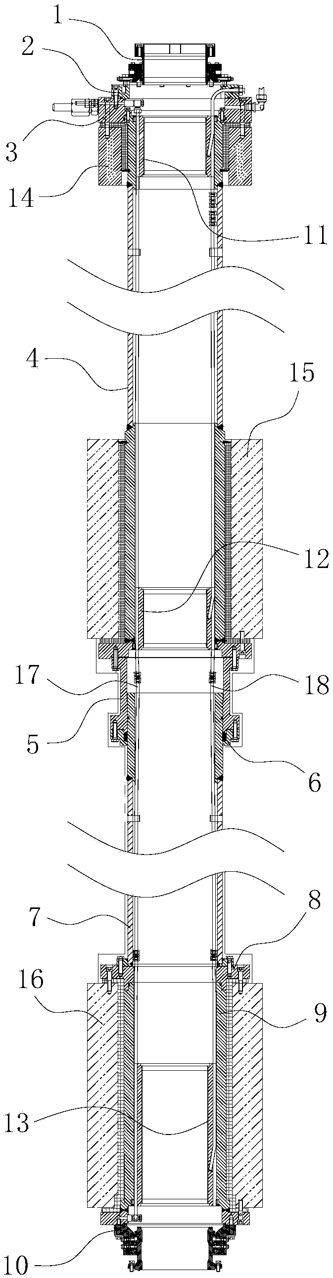
[0028] like figure 1 As shown, this embodiment provides an adjustable-length integrated stern tube device, which mainly includes a bow sealing device 1, a front gland 2, a first flange 3, a front stern tube 4, a loose joint 5, a packing Gland 6, middle stern tube 7, epoxy gland 8, rear stern tube 9 and stern sealing device 10. The first flange 3 is installed on the front end of the front stern tube 4, the bow sealing device 1 is installed on the first flange 3 thr...


PUM


Abstract

The invention provides a length-adjustable integral stern shaft tube device. The length-adjustable integral stern shaft tube device includes a bow sealing device, a front gland, a first flange, a front stern tube, a loose sleeve joint, a packing gland, an intermediate stern tube, an epoxy gland, a rear stern tube and a stern sealing device. The first flange is installed at the front end of the front stern tube. The bow sealing device is installed on the first flange through the front gland. The tail end of the front stern tube is connected with the front end of the loose sleeve joint. The loose sleeve joint is provided with a through connecting cavity. The front end of the middle stern tube is inserted into the connecting cavity from the tail end of the loose sleeve joint. The middle sterntube is sleeved with the packing gland to adjust the depth of the middle stern tube inserted into the connecting cavity. The packing gland is connected with the tail end of the loose sleeve joint. The tail end of the middle stern tube is connected with the front end of the rear stern tube in butt joint mode through the epoxy gland. The stern sealing device is installed at the rear end of the rearstern tube. Compared with the prior art, the stern shaft tube device has the advantages of high installation accuracy, convenient operation, good applicability and the like.

Description

technical field [0001] The invention relates to the technical field of ship stern shafts, in particular to an adjustable-length integral stern shaft tube device. Background technique [0002] The stern shaft is the key equipment for the ship to output propulsion power, and its operating status is related to the navigation safety of the entire ship. In modern ships, the stern shaft is generally installed on the stern of the ship through the stern tube device. Since the stern shaft carries the power to propel the entire ship forward, the stern shaft must have high strength, good lubricity, and stable operation. The stern shaft tube device with accurate installation and good sealing is the guarantee for the good operation of the stern shaft. [0003] In the past, the stern tube device was carried out in the slipway and dock for high-precision operations such as boring and press-fitting bearings. Due to the complex construction environment and limited construction conditions in...

Claims


Application Information

Patent Timeline
IPC IPC(8): B63H23/36
CPCB63H23/36
Inventor 屈莲娥陈伟林
Owner CSSC HUANGPU WENCHONG SHIPBUILDING COMPANY
Features
  • R&D
  • Intellectual Property
  • Life Sciences
  • Materials
  • Tech Scout
  • Unparalleled Data Quality
  • Higher Quality Content
  • 60% Fewer Hallucinations
Learn More