Spray code identification method and identification apparatus
A recognition method and coding technology, applied in the field of coding recognition, can solve the problems of computing efficiency and calculation accuracy, low code and algorithm reuse rate, etc.
- Summary
- Abstract
- Description
- Claims
- Application Information
AI Technical Summary
Problems solved by technology
Method used
Image


Examples
Embodiment 1
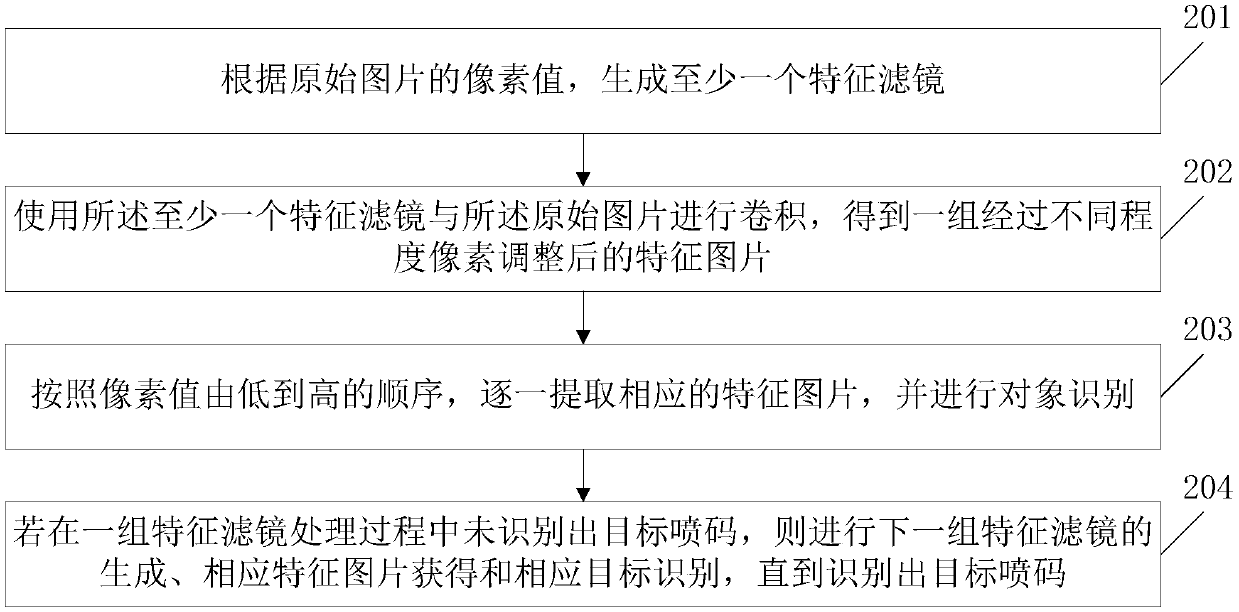
[0082] Embodiment 1 of the present invention provides a coding recognition method. First, it is necessary to obtain the original picture carrying the coding to be recognized. The acquisition method is usually through one or more cameras installed on the assembly line, from one or more angles captured, such as figure 1 As shown, the coding identification method includes:
[0083] In step 201, at least one feature filter is generated according to the pixel values of the original picture.
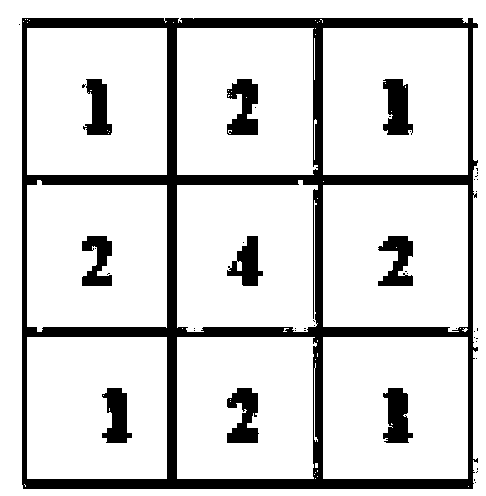
[0084] Wherein, the at least one feature filter is arranged from high to low according to its pixel value. The pixel value size of the feature filter can be a feature filter with a size of 3×3 pixels (such as figure 2 As shown), it can also be a feature filter with a size of 5×5 pixels, or a feature filter with a size of 9×9 pixels, where the pixel gap between different feature filters is related to the resolution of the camera that acquires the original image Even, usually, the higher t...
Embodiment 2
[0115] The embodiment of the present invention also provides a coding recognition method. Compared with the coding recognition method described in Embodiment 1, both of them have in common that a feature filter is used, and the features processed by the feature filter are The picture completes the identification of the target inkjet code. However, in Embodiment 1, a similar pyramid idea is used, that is, the recognition process in the next-level feature picture uses the recognition result of the previous level or multi-level feature pictures, so that the calculation Compared with the existing technology, the complexity is greatly reduced; and the embodiment of the present invention further simplifies the method idea from the calculation process, and at the expense of the calculation complexity, a concurrent processing method is used to perform batch feature Recognition of the object in the picture, and finally obtain the target coding area, avoiding the need to consider whether...
Embodiment 3
[0138] The embodiment of the present invention also provides a code recognition device, such as Figure 11 As shown, it includes a feature filter generation module, a feature image generation module, an object recognition module and a target inkjet recognition module. Each module is connected in sequence, specifically:
[0139] The feature filter generation module is used to generate at least one feature filter according to the pixel values of the original image.
[0140] A feature picture generating module, configured to use the at least one feature filter to perform convolution with the original picture to obtain a set of feature pictures after pixel adjustments of different degrees.
[0141] Wherein, the larger the pixel value of the feature filter, the higher the degree of blurring of the obtained feature image;
[0142] The object recognition module is used to extract corresponding feature pictures one by one according to the order of pixel values from low to high, a...
PUM
 Abstract
Description
Claims
Application Information
 - R&D
- Intellectual Property
- Life Sciences
- Materials
- Tech Scout
- Unparalleled Data Quality
- Higher Quality Content
- 60% Fewer Hallucinations
Browse by: Latest US Patents, China's latest patents, Technical Efficacy Thesaurus, Application Domain, Technology Topic, Popular Technical Reports.
© 2025 PatSnap. All rights reserved.Legal|Privacy policy|Modern Slavery Act Transparency Statement|Sitemap|About US| Contact US: help@patsnap.com